G4ODC5FM OPTO 22, G4ODC5FM Datasheet - Page 17
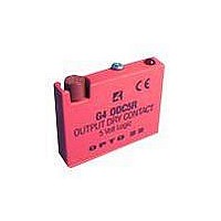
G4ODC5FM
Manufacturer Part Number
G4ODC5FM
Description
I/O Module
Manufacturer
OPTO 22
Datasheet
1.G4ODC5FM.pdf
(68 pages)
Specifications of G4ODC5FM
Leaded Process Compatible
No
Peak Reflow Compatible (260 C)
No
No. Of Analog Outputs
1
Signal Input Type
4 To 8VDC
Supply Voltage
5V
No. Of Outputs
1
Lead Free Status / RoHS Status
Contains lead / RoHS non-compliant


Specifications
Dimensions—G4PB8H
Connections—G4PB8H
Operating temperature
Interface connectors
Field:
Control:
Power:
0
Screw-type barrier strip accommodates up to 10 AWG wire
50-pin header connector
Two-position screw terminal or Opto 22 PBSA/B/C power supply
°
to 70
°
C
Notes:
1. Even pins on control
2. +VCC and return connected to
3. At each module position on
4. Use only 5 VDC logic modules
connector are connected by
etch to common.
terminals marked +5V and
GND.
the field terminal strip, the
lower number is always
connected to pin 1 of the I/O
module.
when using the mounting rack
with a brain board.
CHAPTER 2: GENERATION 4 DIGITAL I/O MOUNTING RACKS
G4 Digital I/O Family Data Book
Position
Module
0
1
2
3
4
5
6
7
Connector)
(Header
Control
47
45
43
41
39
37
35
33
(Terminal Strip)
11 and 12
13 and 14
15 and 16
9 and 10
1 and 2
3 and 4
5 and 6
7 and 8
Field
9
9
Related parts for G4ODC5FM
Image
Part Number
Description
Manufacturer
Datasheet
Request
R

Part Number:
Description:
DC Output Module
Manufacturer:
OPTO 22
Datasheet:

Part Number:
Description:
SSR, PANEL MOUNT, 280VAC, 32VDC, 10A
Manufacturer:
OPTO 22
Datasheet:

Part Number:
Description:
SSR, PANEL MOUNT, 280VAC, 32VDC, 25A
Manufacturer:
OPTO 22
Datasheet:
Part Number:
Description:
SSR, PANEL MOUNT, 280VAC, 32VDC, 25A
Manufacturer:
OPTO 22
Datasheet:
Part Number:
Description:
SSR, PANEL MOUNT, 280VAC, 32VDC, 45A
Manufacturer:
OPTO 22
Datasheet:
Part Number:
Description:
SSR, PANEL MOUNT, 280VAC, 32VDC, 45A
Manufacturer:
OPTO 22
Datasheet:

Part Number:
Description:
SSR, 10A, 240VAC
Manufacturer:
OPTO 22
Datasheet:

Part Number:
Description:
Programmable Logic Controller
Manufacturer:
OPTO 22
Datasheet:

Part Number:
Description:
Programmable Logic Controller
Manufacturer:
OPTO 22
Datasheet:

Part Number:
Description:
Solid State Relays, Accessories
Manufacturer:
OPTO 22
Datasheet:
