LS32P41B11 ABB, LS32P41B11 Datasheet - Page 6
LS32P41B11
Manufacturer Part Number
LS32P41B11
Description
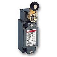
LIMIT SWITCH, ROLLER PLUNGER
Manufacturer
ABB
Datasheet
1.LS32P11B11.pdf
(94 pages)
Specifications of LS32P41B11
Contact Voltage Ac Max
400V
Contact Voltage Dc Max
250V
Contact Current Ac Max
10A
Contact Current Dc Max
4A
Switch Terminals
Screw
Svhc
No SVHC (18-Jun-2010)
Actuator Type
Roller Plunger


Applications
Easy to use, electromechanical limit switches offer specific qualities:
●
●
●
●
●
●
They are exceptional detection devices thanks to these characteristics:
●
●
●
Description
Limit switches, which are made of zinc alloy (zamack), have a degree of protection of IP66.
The casings come in 2 dimensions:
Type
4
1SBC141138C0201
Casing:
●
●
Mounting the casing:
●
●
Electrical connection:
●
●
●
●
●
Terminal for protective conductor placed near the
cable inlet and marked:
●
Limit Switch ................................................................................ LS
Casing width: 30 mm .................................................................................... 3
1 cable inlet M16 x 1.5 for ISO 16 cable gland .................................................... 2
1 cable inlet M20 x 1.5 for ISO 20 cable gland .................................................... 3
1 cable inlet 1/2" NPT for 1/2" NPT cable gland .................................................. 5
Casing width: 60 mm (new casing) .............................................................. 7
3 cable inlets M16 x 1.5 for ISO 16 cable gland .................................................. 2
3 cable inlets M20 x 1.5 for ISO 20 cable gland .................................................. 3
3 cable inlets 1/2" NPT for 1/2" NPT cable gland ................................................ 5
Metal casing ..................................................................................................................... M
>> Travel and Operation Diagrams .................................................................... page 8
>> General Technical Data .................................................................................. page 9
Visible operation.
Able to switch strong currents (10 A conventional thermal current).
Electrically separated contacts (Zb shape).
Contact blocks with positive opening operation of the "N.C." normally closed contact(s) (symbol
Precise operating points (consistency).
Immune to electromagnetic disturbances.
Presence/absence.
Positioning and travel limit.
Objects passing/counting.
30 mm width with standardized dimension according to
EN 50047
60 mm width
2 x M4 screws for 30 mm width
2 or 4 x M4 screws for 60 mm width
1 (LS32M) or 3 (LS72M) cable inlets M16 x 1.5 for ISO 16
cable gland
1 (LS33M) or 3 (LS73M) cable inlets M20 x 1.5 for ISO 20
cable gland
1 (LS35M) or 3 (LS75M) x 1/2" NPT cable gland
Other cable entries (Pg13.5, Pg11) on request
Suitable for conduit connection only with use of adaptor
sleeve optionally provided by manufacturer. (on request)
M3.5 (+,–) pozidriv 2 screw
(Screw head with captive cable clamp)
Example:
LS32M..., LS33M..., LS35M... and
LS72M..., LS73M..., LS75M... Limit Switches
Metal Casing IP66
– LS32M..., LS33M..., LS35M... 30 mm width.
– LS72M..., LS73M..., LS75M... 60 mm width.
L S
L S
3 2
M
M
4 1
Operating heads:
10 ... 98 ........................................................................................................................ Codes
>> Terminology ................................................................................................... page 50
>> Ordering Details ................................................................................... pages 52...67
B 1 1
Snap action:
B ........... Zb Snap
Dependent (slow) action:
L ........... Zb Slow / Simultaneous
D ........... Zb Non-overlapping late make
C ........... Zb Overlapping early make
Contact types:
11 ........... 1 N.O. + 1 N.C. contacts
20 ........... 2 N.O. contacts
02 ........... 2 N.C. contacts
Block of 2 contacts:
●
●
●
●
Connecting terminals:
●
●
A variety of operating heads:
●
●
●
Assembled using 4 x M3 screws for 30 & 60 mm widths
Cover:
●
●
One piece sealing gasket to ensure tightness
Contact configuration: 1 N.O. + 1 N.C. or 2 N.O. or 2 N.C.
Positive opening operation
Snap action or slow action
Zb shape: the 2 contacts are electrically separated
M3.5 (+,–) pozidriv 2 screw
(Screw head with captive cable clamp)
Markings conform with IEC 60947-1, IEC 60947-5-1,
EN 50005 and EN 50013 standards
Plain plunger
Roller plunger
Roller lever, adjustable or not, etc.
Closed using 3 x M3 screws for 30 mm width
Closed using 4 x M3 screws for 60 mm width
).
Low Voltage Products
Related parts for LS32P41B11
Image
Part Number
Description
Manufacturer
Datasheet
Request
R

Part Number:
Description:
ABB Entrelec Inc - S282UC-K10 - Circuit Breaker 500V DC 2 Pol 10A ...
Manufacturer:
ABB
Part Number:
Description:
FAN, ABB SOFTSTARTER
Manufacturer:
ABB
Datasheet:

Part Number:
Description:
IC, VOLTAGE DETECTOR, 8µA, 24V, SOT-89-5
Manufacturer:
Seiko Instruments
Datasheet: