LS32P41B11 ABB, LS32P41B11 Datasheet - Page 10
LS32P41B11
Manufacturer Part Number
LS32P41B11
Description
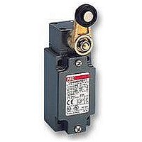
LIMIT SWITCH, ROLLER PLUNGER
Manufacturer
ABB
Datasheet
1.LS32P11B11.pdf
(94 pages)
Specifications of LS32P41B11
Contact Voltage Ac Max
400V
Contact Voltage Dc Max
250V
Contact Current Ac Max
10A
Contact Current Dc Max
4A
Switch Terminals
Screw
Svhc
No SVHC (18-Jun-2010)
Actuator Type
Roller Plunger


P
position of the switch actuator when no external
force is exerted on it.
P
position of the switch actuator, under the effect
of force F1, when the contacts leave their initial
free position.
P
position of the switch actuator from which
positive opening is ensured.
L
maximum acceptable travel position of the
switch actuator under the effect of a force F1.
P
position of the switch actuator when the
contacts return to their initial free position.
C
distance between the free position P
the operating position P
8
1SBC141138C0201
O
A
P
R
1
>> Panorama .................................................................................................. pages 2...3
>> Additional Technical Data ................................................................... pages 12...48
>> Ordering Details ................................................................................... pages 52...76
Note:
Examples:
LS32M13B11
(snap action contacts)
LS32M41B11
(snap action contacts)
LS32M11D11
(non-overlapping slow action contacts)
Free position:
Operating position:
Positive opening position:
Max. travel position:
Release position:
Pre-travel (average travel):
P
for slow action contacts, C
O
C
P
A
F1
A
.
3
C
C: Travel in millimetres
Limit Switches Plastic or Metal Casing
Travel and Operation Diagrams
= 0, C
O
and
1-1
= pre-travel of contact 21-22, C
P
P
C
minimum travel of the switch actuator, from the
free position, to ensure positive opening
operation of the normally closed contact (N.C.).
C
distance between the operating position P
the max. travel position L.
C
distance between the free position P
max. travel position L.
C
travel difference of the switch actuator between
the operating position P
tion P
C
distance between the release position P
the free position P
P
2
L
3
4
Positive opening travel:
Over-travel (average travel):
Max. travel (maximum travel):
Differential travel (C1-C4) (average travel):
Release travel (average travel):
R
.
L
C
O
.
A
and the release posi-
>> Standards ...................................................................................................... page 49
>> Terminology and Utilization Precautions ........................................... pages 50...51
P
1-2
R
= pre-travel of contact 13-14.
21-22
13-14
21-22
13-14
21-22
13-14
21-22
13-14
21-22
13-14
Diagram in millimetres/cam travel
Diagram in degrees/lever rotation
Diagram in millimetres/plunger travel
O
0
0
0
and the
17°
3.0
R
1.9 3.5
A
4.8
31°
and
and
2.8
7.7
47°
9.6 mm
74°
5.6 mm
Contacts position
Diagram for snap action contacts:
21-22
13-14
21-22
13-14
Diagram for non-overlapping
21-22
13-14
C
slow action contacts:
4
C
C
C
1-1
C
1
1-2
3
C: Travel in degrees
C
C
P
P
C
C
L
L
P
P
P
P
21-22
21-22
Contacts identification (example)
Low Voltage Products
Actuation
Release
Actuation
and release
Contact closed
Contact open
Related parts for LS32P41B11
Image
Part Number
Description
Manufacturer
Datasheet
Request
R

Part Number:
Description:
ABB Entrelec Inc - S282UC-K10 - Circuit Breaker 500V DC 2 Pol 10A ...
Manufacturer:
ABB
Part Number:
Description:
FAN, ABB SOFTSTARTER
Manufacturer:
ABB
Datasheet:

Part Number:
Description:
IC, VOLTAGE DETECTOR, 8µA, 24V, SOT-89-5
Manufacturer:
Seiko Instruments
Datasheet: