E5CN-Q2MT500-AC100240 Omron, E5CN-Q2MT500-AC100240 Datasheet - Page 9
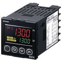
E5CN-Q2MT500-AC100240
Manufacturer Part Number
E5CN-Q2MT500-AC100240
Description
Temperature Controller
Manufacturer
Omron
Datasheet
1.E5CN-Q2M-TD-500_ACDC24.pdf
(15 pages)
Specifications of E5CN-Q2MT500-AC100240
Operating Temperature Max
55°C
Operating Temperature Min
-10°C
Temperature Accuracy ±
0.5%
Output Voltage Max
240VAC
Output Voltage Min
10.2V
Controller Input
Thermocouple Or RTD
Rohs Compliant
Yes
Thermocouple Type
J, K, T, E, L, U, N, R, S, B, W, PLII
Lead Free Status / RoHS Status
Lead free / RoHS Compliant


Characteristics
*1. The indication accuracy of K thermocouples in the −200 to 1300°C range, T and N thermocouples at a temperature of −100°C max., and U
*2. Ambient temperature: −10°C to 23°C to 55°C, Voltage range: −15% to 10% of rated voltage
*3. K thermocouple at −100°C max.: ±10° max.
*4. “EU” stands for Engineering Unit and is used as the unit after scaling. For a temperature sensor, the EU is °C or °F.
*5. When robust tuning (RT) is ON, the differential time is 0.0 to 999.9 (in units of 0.1 s).
*6. External communications (RS-485) and cable communications for the Setup Tool can be used at the same time.
*7. The E5CN-U plug-in model is certified for UL listing only when used together with the OMRON P2CF-11 or P2CF-11-E Socket.
*8. Access the following website for information on certified models. http://www.ia.omron.com/support/models/index.html
*9. Refer to information on maritime standards in Safety Precautions for E5
Indication accuracy
Influence of temperature *2
Influence of voltage *2
Input sampling period
Hysteresis
Proportional band (P)
Integral time (I)
Derivative time (D)
Control period
Manual reset value
Alarm setting range
Affect of signal source
resistance
Insulation resistance
Dielectric strength
Vibration
resistance
Shock
resistance
Weight
Degree of
protection
Memory protection
Setup Tool
Setup Tool port
Standards
EMC
and L thermocouples at any temperatures is ±2°C ±1 digit max. The indication accuracy of the B thermocouple at a temperature of 400°C max.
is not specified. The indication accuracy of B thermocouples in the 400 to 800°C range is ±3°C max. The indication accuracy of the R and S
thermocouples at a temperature of 200°C max. is ±3°C ±1 digit max. The indication accuracy of W thermocouples is ±0.3 of PV or ±3°C,
whichever is greater, ±1 digit max. The indication accuracy of PL II thermocouples is ±0.3 of PV or ±2°C, whichever is greater, ± 1 digit max.
The P3GA-11 is not certified for UL listing.
Malfunction
Destruction
Malfunction
Destruction
E5CN
E5CN-U
E5CN
E5CN-U
Approved
standards *7
Conformed
standards
Thermocouple: *1
Platinum resistance thermometer input:
Analog input:
CT input:
Thermocouple input (R, S, B, W, PL II):
Other thermocouple input: *3
Platinum resistance thermometer input:
Analog input:
250 ms
Models with thermocouple/platinum resistance thermometer input (universal input): 0.1 to 999.9 EU (in units of 0.1 EU) *4
Models with analog input: 0.01 to 99.99% FS (in units of 0.01% FS)
Models with thermocouple/platinum resistance thermometer input (universal input): 0.1 to 999.9 EU (in units of 0.1 EU) *4
Models with analog input: 0.1 to 999.9% FS (in units of 0.1% FS)
0 to 3999 s (in units of 1 s)
0 to 3999 s (in units of 1 s) *5
0.5, 1 to 99 s (in units of 1 s)
0.0 to 100.0% (in units of 0.1%)
−1999 to 9999 (decimal point position depends on input type)
Thermocouple: 0.1°C/Ω max. (100 Ω max.)
Platinum resistance thermometer: 0.1°C/Ω max. (10 Ω max.)
20 MΩ min. (at 500 VDC)
2,300 VAC, 50 or 60 Hz for 1 min (between terminals with different charge)
10 to 55 Hz, 20 m/s
10 to 55 Hz, 0.75-mm single amplitude for 2 hrs each in X, Y, and Z directions
100 m/s
300 m/s
Controller: Approx. 150 g, Mounting Bracket: Approx. 10 g
Controller: Approx. 110 g, Mounting Bracket: Approx. 10 g
Front panel: IP66, Rear case: IP20, Terminals: IP00
Front panel: IP50, Rear case: IP20, Terminals: IP00
Non-volatile memory (number of writes: 1,000,000 times)
CX-Thermo version 4.0 or higher
Provided on the bottom of the E5CN. Use this port to connect a computer to the E5CN when using the Setup Tool. An E58-CIFQ1
USB-Serial Conversion Cable is required to connect the computer to the E5CN. *6
UL 61010-1, CSA C22.2 No. 1010-1, KOSHA certified (some models) *8
EN 61010-1 (IEC 61010-1): Pollution level 2, overcurrent category II
EMI:
Radiated Interference Electromagnetic Field Strength: EN 55011 Group 1, class A
Noise Terminal Voltage:
EMS:
ESD Immunity:
Electromagnetic Field Immunity:
Burst Noise Immunity:
Conducted Disturbance Immunity:
Surge Immunity:
Power Frequency Magnetic Field Immunity:
Voltage Dip/Interrupting Immunity:
Terminal block models (E5CN): (±0.3% of indicated value or ±1°C, whichever is greater) ±1 digit max.
Plug-in models (E5CN-U): (±1% of indicated value or ±2°C, whichever is greater) ±1 digit max.
Terminal block models (E5CN) and plug-in models (E5CN-U): (±0.2% of indicated value or ±0.8°C, whichever is greater) ±1 digit max.
Terminal block models (E5CN) and plug-in models (E5CN-U): ±0.2% FS ±1 digit max.
Terminal block models (E5CN): ±5% FS ±1 digit max.
Terminal block models (E5CN): (±1% of PV or ±10°C, whichever is greater) ±1 digit max.
Plug-in models (E5CN-U): (±2% of PV or ±10°C, whichever is greater) ±1 digit max.
Terminal block models (E5CN): (±1% of PV or ±4°C, whichever is greater) ±1 digit max.
Plug-in models (E5CN-U): (±2% of PV or ±4°C, whichever is greater) ±1 digit max.
Terminal block models (E5CN) and plug-in models (E5CN-U):
(±1% of PV or ±2°C, whichever is greater) ±1 digit max.
Terminal block models (E5CN) and plug-in models (E5CN-U): (±1%FS) ±1 digit max.
2
2
, 3 times each in X, Y, and Z directions
, 3 times each in X, Y, and Z directions
2
for 10 min each in X, Y, and Z directions
@
N/E5
EN 61326
EN 55011 Group 1, class A
EN 61326
EN 61000-4-2
EN 61000-4-3
EN 61000-4-4
EN 61000-4-6
EN 61000-4-5
EN 61000-4-8
EN 61000-4-11
@
N-H for compliance with Lloyd's Standards.
, Lloyd's standards *9
E5CN/E5CN-U
9
Related parts for E5CN-Q2MT500-AC100240
Image
Part Number
Description
Manufacturer
Datasheet
Request
R

Part Number:
Description:
TEMPERATURE CONTROL, DIGITAL
Manufacturer:
Omron
Datasheet:

Part Number:
Description:
Old,Use E5CN-Q2MT-500 AC100240
Manufacturer:
Omron
Part Number:
Description:
Multi Input 1/16 Din TC New08
Manufacturer:
Omron

Part Number:
Description:
G6S-2GLow Signal Relay
Manufacturer:
Omron Corporation
Datasheet:
Part Number:
Description:
Compact, Low-cost, SSR Switching 5 to 20 A
Manufacturer:
Omron Corporation
Datasheet:
Part Number:
Description:
Manufacturer:
Omron Corporation
Datasheet:
Part Number:
Description:
Manufacturer:
Omron Corporation
Datasheet:
Part Number:
Description:
Manufacturer:
Omron Corporation
Datasheet:
Part Number:
Description:
Manufacturer:
Omron Corporation
Datasheet:
Part Number:
Description:
Manufacturer:
Omron Corporation
Datasheet: