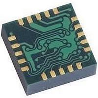
HMC5843 Honeywell Microelectronics & Precision Sensors, HMC5843 Datasheet - Page 14

HMC5843
Manufacturer Part Number
HMC5843
Description
Magnetic Sensor
Manufacturer
Honeywell Microelectronics & Precision Sensors
Datasheet
1.HMC5843.pdf
(21 pages)
Specifications of HMC5843
Msl
MSL 3 - 168 Hours
Sensitivity Range
+/- 10 %
Sensor Terminals
PCB
Magnetic Field Max
4G
Axis Configuration
Three
Sensor Output
Digital
Available stocks
Company
Part Number
Manufacturer
Quantity
Price
Company:
Part Number:
HMC5843
Manufacturer:
HITTITE
Quantity:
3 000
Company:
Part Number:
HMC5843-DEMO
Manufacturer:
Honeywell Microelectronics & P
Quantity:
135
Company:
Part Number:
HMC5843-EVAL
Manufacturer:
Honeywell Microelectronics & P
Quantity:
135
HMC5843
Register Access
This section describes the process of reading from and writing to this device. The devices uses an address pointer to
indicate which register location is to be read from or written to. These pointer locations are sent from the master to this
slave device and succeed the 7-bit address plus 1 bit read/write identifier.
To minimize the communication between the master and this device, the address pointer updated automatically without
master intervention. This automatic address pointer update has two additional features. First when address 12 or higher
is accessed the pointer updates to address 00 and secondly when address 08 is reached, the pointer rolls back to
address 03. Logically, the address pointer operation functions as shown below.
If (address pointer = 08) then address pointer = 03
Else if (address pointer >= 12) then address pointer = 0
Else (address pointer) = (address pointer) + 1
The address pointer value itself cannot be read via the I
Any attempt to read an invalid address location returns 0’s, and any write to an invalid address location or an undefined bit
within a valid address location is ignored by this device.
Configuration Register A
The configuration register is used to configure the device for setting the data output rate and measurement configuration.
CRA0 through CRA7 indicate bit locations, with CRA denoting the bits that are in the configuration register. CRA7 denotes
the first bit of the data stream. The number in parenthesis indicates the default value of that bit.
The Table below shows minimum output data rates given PVT conditions. All three channels shall be measured within a
given data rate.
14
CRA7
(0)
Location
CRA7 to CRA5
CRA4 to CRA2
CRA1 to CRA0
DO2
0
0
0
0
1
1
1
1
DO1
0
0
1
1
0
0
1
1
CRA6
(0)
DO0
0
1
0
1
0
1
0
1
Table 7: Configuration Register A Bit Designations
Name
0
DO2 to DO0
MS1 to MS0
Minimum Data Output Rate (Hz)
0.5
1
2
5
10 (default)
20
50
Not used
CRA5
(0)
Table 6: Configuration Register A
Table 8: Data Output Rates
CRA4
DO2 (1)
Description
These bits must be cleared for correct operation.
Data Output Rate Bits. These bits set the rate at which
data is written to all three data output registers.
Measurement Configuration Bits. These bits define the
measurement flow of the device, specifically whether or
not to incorporate an applied bias to the sensor into the
measurement.
2
C bus.
CRA3
DO1 (0)
CRA2
DO0 (0)
CRA1
MS1 (0)
CRA0
MS0 (0)
www.honeywell.com


