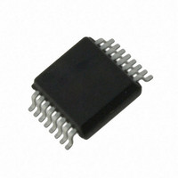
AS5043-ASST austriamicrosystems, AS5043-ASST Datasheet - Page 21

AS5043-ASST
Manufacturer Part Number
AS5043-ASST
Description
IC ENCODER PROG 10-BIT 16-SSOP
Manufacturer
austriamicrosystems
Type
Linear, Rotary Encoder - Programmabler
Datasheet
1.AS5043_PB.pdf
(36 pages)
Specifications of AS5043-ASST
Sensing Range
45mT ~ 75mT
Voltage - Supply
3 V ~ 3.6 V, 4.5 V ~ 5.5 V
Current - Supply
21mA
Current - Output (max)
4mA
Output Type
Analog, Digital
Features
Programmable
Operating Temperature
-40°C ~ 125°C
Package / Case
16-SSOP
Lead Free Status / RoHS Status
Lead free / RoHS Compliant
Other names
AS5043-ASSTTR
AS5043
Data Sheet – Choosing the Proper Magnet
15.1.1 Magnet Placement
The magnet’s center axis should be aligned within a displacement radius R
with reference to the edge of pin #1 (see Figure 19). This radius includes the placement tolerance of the chip within the
SSOP-16 package (+/- 0.235mm).
The displacement radius R
The vertical distance should be chosen such that the magnetic field on the die surface is within the specified limits (see
Figure 18). The typical distance “z” between the magnet and the package surface is 0.5mm to 1.8mm with the
recommended magnet (6mm x 3mm). Larger gaps are possible, as long as the required magnetic field strength stays
within the defined limits.
A magnetic field outside the specified range may still produce usable results, but the out-of-range condition will be
indicated by MagRngn (pin 1), which will be pulled low. At this condition, the angular data is still available over the digital
serial interface (SSI), but the analog output will be turned off.
Figure 20: Vertical Placement of the Magnet
www.austriamicrosystems.com
d
is 0.485mm with reference to the center of the chip (see section Alignment Mode).
Die surface
N
Package surface
S
Revision 1.80
z
1.282mm ± 0.15mm
0.576mm ± 0.1mm
d
of 0.25mm from the defined center of the IC
21 – 36


