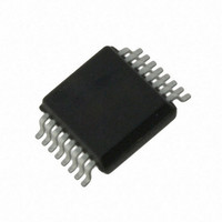
AS5043-ASST austriamicrosystems, AS5043-ASST Datasheet - Page 12

AS5043-ASST
Manufacturer Part Number
AS5043-ASST
Description
IC ENCODER PROG 10-BIT 16-SSOP
Manufacturer
austriamicrosystems
Type
Linear, Rotary Encoder - Programmabler
Datasheet
1.AS5043_PB.pdf
(36 pages)
Specifications of AS5043-ASST
Sensing Range
45mT ~ 75mT
Voltage - Supply
3 V ~ 3.6 V, 4.5 V ~ 5.5 V
Current - Supply
21mA
Current - Output (max)
4mA
Output Type
Analog, Digital
Features
Programmable
Operating Temperature
-40°C ~ 125°C
Package / Case
16-SSOP
Lead Free Status / RoHS Status
Lead free / RoHS Compliant
Other names
AS5043-ASSTTR
AS5043
Data Sheet – Programming the AS5043
12 Programming the AS5043
After power-on, programming the AS5043 is enabled with the rising edge of CSn and Prog = logic high. 16 bit
configuration data must be serially shifted into the OTP register via the Prog-pin. The first “CCW” bit is followed by the
zero position data (MSB first) and the Analog Output Mode setting as shown in Table 5. Data must be valid at the rising
edge of CLK (see Figure 10). Following this sequence, the voltage at pin Prog must be raised to the programming voltage
V
chip must be reset by a power-on-reset. The programmed data is available after the next power-up.
Note: During the programming process, the transitions in the programming current may cause high voltage spikes
generated by the inductance of the connection cable. To avoid these spikes and possible damage to the IC, the
connection wires, especially the signals PROG and VSS must be kept as short as possible. The maximum wire length
between the V
To suppress eventual voltage spikes, a 10nF ceramic capacitor should be connected close to pins PROG and VSS. This
capacitor is only required for programming, it is not required for normal operation. The clock timing t
a proper rate to ensure that the signal PROG is stable at the rising edge of CLK (see Figure 10). Additionally, the
programming supply voltage should be buffered with a 10µF capacitor mounted close to the switching transistor. This
capacitor aids in providing peak currents during programming. The specified programming voltage at pin PROG is 7.3 –
7.5V (see section 19.7). To compensate for the voltage drop across the V
programming voltage may be set slightly higher (7.5 - 8.0V, see Figure 12).
OTP Register Contents:
CCW
Z [9:0]: Programmable Zero / Index Position
FB_intEN: OPAMP gain setting: 0=external, 1=internal
RefExtEN: DAC reference: 0=internal, 1=external
ClampMd EN:
Output Range (OR0, OR1):
Figure 10: Programming Access – OTP Write Cycle (section of)
www.austriamicrosystems.com
PROG
(see Figure 10). 16 CLK pulses (t
CLK
Counter Clockwise Bit
ccw=0 – angular value increases with clockwise rotation
ccw=1 – angular value increases with counterclockwise rotation
Analog Output Range Selection
[1:0]
Prog
CSn
PROG
PROG
t
Prog enable
Analog output span: 0=0-100%,
1=10-90%*VDD
00 = 360°
10 = 90°
switching transistor and pin PROG (see Figure 12) should not exceed 50mm (2 inches).
t
Datain
CCW
t
1
Datain valid
Z9
01 = 180°
11 = 45°
see text
Z8
t
clk
PROG
Z7
) must be applied to program the fuses. To exit the programming mode, the
Z6
Zero Position
Z5
Revision 1.80
Z4
Z3
8
Z2
Z1
Z0
PROG
FB_int
EN
switching transistor, the applied
RefExt
EN
Analog Modes
Clamp
Md En
clk
Range1
Output
must be selected at
Range0
Output
16
12 – 36


