MXC62020MP MEMSIC, MXC62020MP Datasheet
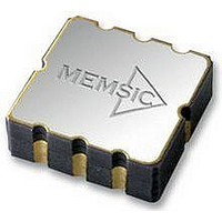
ACCELEROMETER, 2 AXIS, ±2.0G, I2C

MXC62020MP

Manufacturer Part Number
MXC62020MP
Description
ACCELEROMETER, 2 AXIS, ±2.0G, I2C
Manufacturer
MEMSIC
Datasheet

Specifications of MXC62020MP

No. Of Axes
2
Sensor Case Style
LCC
No. Of Pins
8
Supply Voltage Range
2.7V To 3.6V
Operating Temperature Range
-40°C To +85°C
Operating Temperature Max
85°C
Operating
RoHS Compliant
Acceleration Range
±2g

Available stocks

Company
Part Number
Manufacturer
Quantity
Price
Part Number:
MXC62020MP
Manufacturer:
ATT
Quantity:
5 624
Part Number:
MXC62020MP
Manufacturer:
MEMSIC
Quantity:
20 000
FEATURES
RoHS compliant
I
1.8V compatible IO
Embedded Power up/down and self-test function
On-chip temperature sensor available
Eight customer defined 7-bit addresses
2.7 V to 3.6 V single supply continuous operation
Monolithic CMOS IC
Low power consumption: typically <2 mA @ 3.0 V
Resolution better than 1 mg
On chip mixed signal processing
>50,000 g shock survival rating
Low profile LCC package: 5mm X 5mm X 1.55mm
APPLICATIONS
Information Appliances – Cell Phones, PDA’s, Computer
Peripherals
Consumer – LCD Projectors, Pedometers, Blood Pressure
Gaming – Joystick/RF Interface/Menu Selection/Tilt
Sensing
GPS
Reckoning Assist
GENERAL DESCRIPTION
The MXC6202xG/H/M/N is low cost, dual axis
accelerometers fabricated on a standard, submicron CMOS
process. It is a complete sensing system with on-chip
mixed signal processing and integrated I
the device to be connected directly to a microprocessor
eliminating the need for A/D converters or timing
resources. The MXC6202xG/H/M/N measures acceleration
with a full-scale range of ±2 g and a sensitivity of
512counts/g (G/M) or 128counts/g (H/N) @3.0 V at 25
It can measure both dynamic acceleration (e.g. vibration)
and static acceleration (e.g. gravity). The
MXC6202xG/H/M/N design is based on heat convection
and requires no solid proof mass.
Information furnished by MEMSIC is believed to be accurate and reliable. However,
no responsibility is assumed by MEMSIC for its use, or for any infringements of
patents or other rights of third parties which may result from its use. No license is
granted by implication or otherwise under any patent or patent rights of MEMSIC.
MEMSIC MXC6202xG/H/M/N Rev.C
2
C Slave, FAST (≤400 KHz.) mode interface
Electronic Compass Tilt Correction, Dead
Monitor, Digital Cameras
2
C bus, allowing
Low Power, Low Profile
±2 g Dual Axis Accelerometer with
I
2
C Interface
°C
Page 1 of 10
.
This design eliminates the stiction problems associated with
legacy technologies and provides shock survival greater
than 50,000g’s. Memsic’s solid state design leads to
significantly lower failure rates in customer applications
and lower loss due to handling during manufacturing and
assembly processes
The MXC6202xG/H/M/N is packaged in a hermetically
sealed, low profile LCC surface mount package (5 mm x 5
mm x 1.55 mm) and is available in operating temperature
ranges of 0°C to +70°C (G/H) and-40°C to +85°C(M/N).
The MXC6202xG/H/M/N provides I
400 KHz, fast mode operation.
The maximum noise floor is 1 mg/ Hz allowing signals
below 1mg to be resolved at 1 Hz bandwidth
©MEMSIC, Inc.
800 Turnpike St., Suite 202, North Andover, MA01845, USA
Tel: 978.738.0900
www.memsic.com
MXC6202xG/H/M/N FUNCTIONAL BLOCK DIAGRAM
PD
TP
CLK
Acceleration
MXC6202xG/H/M/N
Sensor
Heater
Control
CLK
Oscillator
Internal
Y aixs
X aixs
TEMP
Gain Adj.
Coarse
Gain Adj.
Coarse
CLK
CLK
VDD
Fax: 978.738.0196
GND
CLK TEMP CLK
CLKTEMP
Fine Gain
Fine Gain
VREF
Temp
Comp.
Temp
Adj.
Comp.
Adj.
A/D
A/D
CLK
2
C digital output with
Temperature
Sensor
TEMP
IIC Convertor
CLK
2/26/2007
SCL
Connect
Connect
SDA
No
No

Related parts for MXC62020MP

MXC62020MP Summary of contents

Page 1

... Information furnished by MEMSIC is believed to be accurate and reliable. However, no responsibility is assumed by MEMSIC for its use, or for any infringements of patents or other rights of third parties which may result from its use. No license is granted by implication or otherwise under any patent or patent rights of MEMSIC. ...

Page 2

... Alignment error is specified as the angle between the true and indicated axis of sensitivity 3 Cross axis sensitivity is the algebraic sum of the alignment and the inherent sensitivity errors 4 Output settled to within ± 17mg MEMSIC MXC6202xG/H/M/N Rev.C (Measurements @ 25°C, Acceleration = 0 g unless otherwise noted; V Conditions Min ±2.0 Each Axis ...

Page 3

... SCL Clock Frequency START Hold Time START Setup Time LOW period of SCL HIGH period of SCL Data Hold Time Data Setup Time Rise Time Fall Time Bus Free Time Between STOP and START STOP Setup Time MEMSIC MXC6202xG/H/M/N Rev.C Symbol Test Condition hys 0.1Vdd< ...

Page 4

... Caution: ESD (electrostatic discharge) sensitive device. MEMSIC MXC6202xG/H/M/N Rev.C I Note: The MEMSIC logo’s arrow indicates the -X sensing C bus I 2 direction of the device. The +Y sensing direction is rotated 90° C bus I away from the +X direction following the right-hand rule. Small 2 C bus I/O circle indicates pin one (1) ...

Page 5

... TYPICAL CHARACTERISTICS UNITS (@ 25°C, V OffsetX Distribution 60% 50% 40% 30% 20% 10% 0% -96 -76 -56 -36 - OffsetX Deviation to Target SensitivityX Distribution 35% 30% 25% 20% 15% 10 -48 -38 -28 - SensitivityX Deviation to Target MEMSIC MXC6202xG/H/M/N Rev.C = 3V) DD 60% 50% 40% 30% 20% 10% Offset (mg -96 -76 35% 30% 25% 20% 15% 10% 5% Sen (mg -48 -38 Page OffsetY Distribution ...

Page 6

... Normalized SensitivityX vs. Temp 1.10 1.08 1.06 1.04 1.02 1.00 0.98 0.96 0.94 0.92 0.90 0.88 -50 -10 30 OffsetX TC Distribution 30% 25% 20% 15% 10 -1.9 -1.3 -0.7 -0.1 MEMSIC MXC6202xG/H/M/N Rev.C 25% 20% 15% 10 110 2.02 T(C) -50 70 110 30% 25% 20% 15% 10% 5% TC(mg/C) 0% 0.5 1.1 1.7 -1.9 ...

Page 7

... An accelerometer uses the force of gravity as an input to determine the inclination angle of an object. A MEMSIC accelerometer is most sensitive to changes in position, or tilt, when the accelerometer’s sensitive axis is perpendicular to the force of gravity, or parallel to the Earth’s surface. Similarly, when the accelerometer’s axis is parallel to the force of gravity (perpendicular to the Earth’ ...

Page 8

... MEMSIC device, the offset change will be within 5mg metal ground plane should be added directly beneath the MEMSIC device. The size of the plane should be similar to the MEMSIC device’s footprint and be as thick as possible. 5. Vias can be added symmetrically around the ground plane ...

Page 9

... After writing code of [xxxxxxx0] into the control register “READ” signal is received, during next 9 clock cycles, the Memsic device being called will transfer 8-bits of data 2 to the I C bus “Acknowledge” by master device is received, the Memsic device will continue to transfer the next byte ...

Page 10

... The delay value depends on the type of Memsic device. Generally speaking, low power products tend to have longer startup time. Fourth cycle: Master device sends a START command followed by calling Memsic device address with a WRITE th (8 SCL, SDA keep low). An “acknowledge” should be sent by Memsic device at the end ...

Related keywords