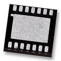
LP3947ISD-51 National Semiconductor, LP3947ISD-51 Datasheet - Page 4

LP3947ISD-51
Manufacturer Part Number
LP3947ISD-51
Description
CHARGER, USB, I2C, POWERWISE, LLP-14
Manufacturer
National Semiconductor
Datasheet
1.LP3947ISD-51.pdf
(14 pages)
Specifications of LP3947ISD-51
Battery Type
Li-Ion
Input Voltage
6V
Battery Charge Voltage
4.2V
Charge Current Max
750mA
Battery Ic Case Style
LLP
No. Of Pins
14
No. Of Series Cells
1
Operating Temperature Range
-40°C
Lead Free Status / RoHS Status
Lead free / RoHS Compliant
Available stocks
Company
Part Number
Manufacturer
Quantity
Price
Company:
Part Number:
LP3947ISD-51/NOPB
Manufacturer:
SONY
Quantity:
6 242
www.national.com
V
V
V
I
V
V
V
BATTERY CHARGER
I
I
I
V
V
CC
CHG
PRE-CHG
EOC
CC
CHG-IN
USB
OK-TSHD
UVLO-TSHD
OVLO-TSHD
BATT
CHG-Q
Absolute Maximum Ratings
2)
If Military/Aerospace specified devices are required,
please contact the National Semiconductor Sales Office/
Distributors for availability and specifications.
Electrical Characteristics
Unless otherwise noted, V
mal type apply for T
T
Symbol
CHG-IN
All pins except GND and CHG-IN
(Note 3)
Junction Temperature
Storage Temperature
Power Dissipation (Note 4)
ESD (Note 5)
J
Human Body Model
Machine Model
= −40˚C to +85˚C. (Notes 7, 8, 9)
SUPPLY
Input Voltage Range
Quiescent Current
Adaptor OK Trip Point (CHG-IN)
Under Voltage Lock-Out Trip Point
Over Voltage Lock-Out Trip Point
Thermal Shutdown Temperature
Thermal Shutdown Hysteresis
Fast Charge Current Range
Fast Charge Current Accuracy
Pre-Charge Current
End of Charge Current Accuracy
Battery Regulation Voltage (For 4.1V
Cell)
Battery Regulation Voltage (For 4.2V
Cell)
Full Charge Qualification Threshold
J
= 25˚C. Limits appearing in boldface type apply over the entire junction temperature range for operation,
Parameter
CHG-IN
= 5V, V
BATT
−40˚C to +150˚C
−0.3V to +6.5V
−0.3V to +6V
= 4V, C
(Notes 1,
V
EOC = Low, adaptor connected,
V
V
V
V
V
V
V
(Note 8)
ISEL = High, In USB Mode
ISEL = Low, In USB Mode
In AC Adaptor Mode
I
I
V
100 mA to 450 mA, 0.1C EOC Only
(Note 10)
500 mA to 750 mA, All EOC Points
T
T
T
T
V
Pre-Charge to Full Current
CHARGE
CHARGE
1.89W
J
J
J
J
CHG-IN
BATT
CHG-IN
CHG-IN
CHG-IN
CHG-IN
CHG-IN
CHG-IN
BATT
BATT
150˚C
CHG-IN
200V
= 0˚C to +85˚C
= −40˚C to +85˚C
= 0˚C to +85˚C
= −40˚C to +85˚C
2 kV
= 4.1V
= 2V
Rising, Transition from
≤ 4V
–V
–V
(Rising)
(Falling)
(Rising)
(Falling)
≥ 200 mA
= 100 mA or 150 mA
= 1 µF, C
4
BATT
BATT
Conditions
Operating Ratings
CHG-IN
EN, ISEL, MODE, SCL, SDA,
V
Junction Temperature
Operating Temperature
Thermal Resistance θ
Maximum Power Dissipation
(Note 6)
(Rising)
(Falling)
T
BATT
(Note 3)
= 10 µF. Typical values and limits appearing in nor-
JA
3.95
3.75
Typ
160
100
500
5.9
5.7
4.1
4.1
4.1
4.2
3.0
50
60
50
20
2
(Notes 1, 2)
4.059
4.038
4.158
4.137
Min
100
−20
−10
−10
−20
4.5
4.3
3.6
3.4
45
Limit
−40˚C to +125˚C
−40˚C to +85˚C
4.141
4.162
4.242
4.263
Max
150
750
+20
+10
+10
+20
0.3V to 6.5V
4.3
4.1
20
70
6
6
0V to 6V
37˚C/W
1.21W
Units
mV
mV
mA
mA
mA
mA
µA
˚C
%
%
V
V
V
V
V
V


