LIS35DETR STMicroelectronics, LIS35DETR Datasheet - Page 17
LIS35DETR
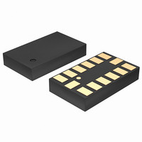
Manufacturer Part Number
LIS35DETR
Description
IC ACCELEROMETER 3AXIS 14LGA
Manufacturer
STMicroelectronics
Datasheet
1.LIS35DETR.pdf
(39 pages)
Specifications of LIS35DETR
Axis
X, Y, Z
Acceleration Range
±2.3g, 9.2g
Sensitivity
18mg/digit, 72mg/digit
Voltage - Supply
2.16 V ~ 3.6 V
Output Type
Digital
Bandwidth
100Hz ~ 400Hz Selectable
Interface
I²C, SPI
Mounting Type
Surface Mount
Package / Case
14-LGA
Sensing Axis
X, Y, Z
Acceleration
2 g, 8 g
Digital Output - Number Of Bits
8 bit
Supply Voltage (max)
3.6 V
Supply Voltage (min)
2.16 V
Supply Current
0.3 mA
Maximum Operating Temperature
+ 85 C
Minimum Operating Temperature
- 40 C
Digital Output - Bus Interface
I2C, SPI
Mounting Style
SMD/SMT
Shutdown
Yes
Lead Free Status / RoHS Status
Lead free / RoHS Compliant
Available stocks
Company
Part Number
Manufacturer
Quantity
Price

Part Number:
LIS35DETR
Manufacturer:
ST
Quantity:
20 000


LIS35DE
5
5.1
Digital interfaces
The registers embedded inside the LIS35DE may be accessed through both the I
SPI serial interfaces. The latter may be SW configured to operate either in 3-wire or 4-wire
interface mode.
The serial interfaces are mapped onto the same pads. To select/exploit the I
line must be tied high (i.e connected to Vdd_IO).
Table 8.
I
The LIS35DE I
whose content can also be read back.
The relevant I
Table 9.
There are two signals associated with the I
Serial DAta line (SDA). The latter is a bidirectional line used for sending and receiving the
data to/from the interface. Both the lines are connected to Vdd_IO through a pull-up resistor
embedded inside the LIS35DE. When the bus is free both the lines are high.
The I
mode.
2
C serial interface
SDA/SDI/SDO
Transmitter
PIN Name
2
SCL/SPC
Receiver
C interface is compliant with fast mode (400 kHz) I
Master
Term
Slave
SDO
CS
Serial interface pin description
Serial interface pin description
2
C terminology is given in the table below.
2
C is a bus slave. The I
SPI enable
I
I
SPI Serial port clock (SPC)
I
SPI serial data input (SDI)
3-wire interface serial data output (SDO)
SPI serial data output (SDO)
The device which sends data to the bus
The device which receives data from the bus
The device which initiates a transfer, generates clock signals and terminates a
transfer
The device addressed by the master
2
2
2
C/SPI mode selection (1: I
C serial clock (SCL)
C serial data (SDA)
Doc ID 15594 Rev 1
2
C is employed to write the data into the registers
2
C bus: the Serial Clock Line (SCL) and the
2
C mode; 0: SPI enabled)
PIN description
Description
2
C standards as well as the normal
Digital interfaces
2
C interface, CS
2
C and
17/39
Related parts for LIS35DETR
Image
Part Number
Description
Manufacturer
Datasheet
Request
R

Part Number:
Description:
STMicroelectronics [RIPPLE-CARRY BINARY COUNTER/DIVIDERS]
Manufacturer:
STMicroelectronics
Datasheet:
Part Number:
Description:
STMicroelectronics [LIQUID-CRYSTAL DISPLAY DRIVERS]
Manufacturer:
STMicroelectronics
Datasheet:

Part Number:
Description:
BOARD EVAL FOR MEMS SENSORS
Manufacturer:
STMicroelectronics
Datasheet:
Part Number:
Description:
NPN TRANSISTOR POWER MODULE
Manufacturer:
STMicroelectronics
Datasheet:
Part Number:
Description:
TURBOSWITCH ULTRA-FAST HIGH VOLTAGE DIODE
Manufacturer:
STMicroelectronics
Datasheet:
Part Number:
Description:
Manufacturer:
STMicroelectronics
Datasheet:
Part Number:
Description:
DIODE / SCR MODULE
Manufacturer:
STMicroelectronics
Datasheet:
Part Number:
Description:
DIODE / SCR MODULE
Manufacturer:
STMicroelectronics
Datasheet:
Part Number:
Description:
Search -----> STE16N100
Manufacturer:
STMicroelectronics
Datasheet:
Part Number:
Description:
Search ---> STE53NA50
Manufacturer:
STMicroelectronics
Datasheet:
Part Number:
Description:
NPN Transistor Power Module
Manufacturer:
STMicroelectronics
Datasheet:
Part Number:
Description:
DIODE / SCR MODULE
Manufacturer:
STMicroelectronics
Datasheet: