LIS35DETR STMicroelectronics, LIS35DETR Datasheet - Page 16
LIS35DETR
Manufacturer Part Number
LIS35DETR
Description
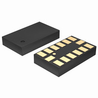
IC ACCELEROMETER 3AXIS 14LGA
Manufacturer
STMicroelectronics
Datasheet
1.LIS35DETR.pdf
(39 pages)
Specifications of LIS35DETR
Axis
X, Y, Z
Acceleration Range
±2.3g, 9.2g
Sensitivity
18mg/digit, 72mg/digit
Voltage - Supply
2.16 V ~ 3.6 V
Output Type
Digital
Bandwidth
100Hz ~ 400Hz Selectable
Interface
I²C, SPI
Mounting Type
Surface Mount
Package / Case
14-LGA
Sensing Axis
X, Y, Z
Acceleration
2 g, 8 g
Digital Output - Number Of Bits
8 bit
Supply Voltage (max)
3.6 V
Supply Voltage (min)
2.16 V
Supply Current
0.3 mA
Maximum Operating Temperature
+ 85 C
Minimum Operating Temperature
- 40 C
Digital Output - Bus Interface
I2C, SPI
Mounting Style
SMD/SMT
Shutdown
Yes
Lead Free Status / RoHS Status
Lead free / RoHS Compliant
Available stocks
Company
Part Number
Manufacturer
Quantity
Price

Part Number:
LIS35DETR
Manufacturer:
ST
Quantity:
20 000


Application hints
4
4.1
16/39
Application hints
Figure 5.
The device core is supplied through Vdd line while the I/O pads are supplied through
Vdd_IO line. Power supply decoupling capacitors (100 nF ceramic, 10 µF Al) should be
placed as near as possible to the pin 6 of the device (common design practice).
All the voltage and ground supplies must be present at the same time to have proper
behavior of the IC (refer to
without blocking the communication busses, in this condition the measurement chain is
powered off.
The functionality of the device and the measured acceleration data is selectable and
accessible through the I
The functions, the threshold and the timing of the two interrupt pins (INT 1 and INT 2) can be
completely programmed by the user though the I
Soldering information
The LGA package is compliant with the ECOPACK®, RoHS and “Green” standard. It is
qualified for soldering heat resistance according to JEDEC J-STD-020C.
Leave “Pin 1 Indicator” unconnected during soldering.
Land pattern and soldering recommendation are available at www.st.com.
Vdd
GND
10uF
100nF
LIS35DE electrical connection
Digital signal from/to signal controller.Signal’s levels are defined by proper selection of Vdd_IO
2
C/SPI interface.When using the I
Figure
Doc ID 15594 Rev 1
8
5). It is possible to remove Vdd maintaining Vdd_IO
6
Top VIEW
2
C/SPI interface.
1
13
2
C, CS must be tied high.
Vdd_IO
Y
DIRECTIONS OF THE
DETECTABLE
ACCELERATIONS
6
TOP VIEW
Z
8
1
LIS35DE
13
X
Related parts for LIS35DETR
Image
Part Number
Description
Manufacturer
Datasheet
Request
R

Part Number:
Description:
STMicroelectronics [RIPPLE-CARRY BINARY COUNTER/DIVIDERS]
Manufacturer:
STMicroelectronics
Datasheet:
Part Number:
Description:
STMicroelectronics [LIQUID-CRYSTAL DISPLAY DRIVERS]
Manufacturer:
STMicroelectronics
Datasheet:

Part Number:
Description:
BOARD EVAL FOR MEMS SENSORS
Manufacturer:
STMicroelectronics
Datasheet:
Part Number:
Description:
NPN TRANSISTOR POWER MODULE
Manufacturer:
STMicroelectronics
Datasheet:
Part Number:
Description:
TURBOSWITCH ULTRA-FAST HIGH VOLTAGE DIODE
Manufacturer:
STMicroelectronics
Datasheet:
Part Number:
Description:
Manufacturer:
STMicroelectronics
Datasheet:
Part Number:
Description:
DIODE / SCR MODULE
Manufacturer:
STMicroelectronics
Datasheet:
Part Number:
Description:
DIODE / SCR MODULE
Manufacturer:
STMicroelectronics
Datasheet:
Part Number:
Description:
Search -----> STE16N100
Manufacturer:
STMicroelectronics
Datasheet:
Part Number:
Description:
Search ---> STE53NA50
Manufacturer:
STMicroelectronics
Datasheet:
Part Number:
Description:
NPN Transistor Power Module
Manufacturer:
STMicroelectronics
Datasheet:
Part Number:
Description:
DIODE / SCR MODULE
Manufacturer:
STMicroelectronics
Datasheet: