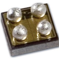
FPF1108 Fairchild Semiconductor, FPF1108 Datasheet

FPF1108
Specifications of FPF1108
Available stocks
Related parts for FPF1108
FPF1108 Summary of contents
Page 1
... QD 55mΩ For Fairchild’s definition of Eco Status, please visit: http://www.fairchildsemi.com/company/green/rohs_green.html. © 2009 Fairchild Semiconductor Corporation FPF1107 / FPF1108 • Rev. 1.0.1 Description The FPF1107/08 are low R switches of the IntelliMAX™ family. Integrated slew-rate control prevents inrush current from glitch supply rails with capacitive loads common in power applications ...
Page 2
... Notes =1μF, X5R, 0603, for example Murata GRM185R60J105KE26 =1μF, X5R, 0805, for example Murata GRM216R61A105KA01 OUT Block Diagram Figure 2. Block Diagram (Output Discharge for FPF1108 Only) © 2009 Fairchild Semiconductor Corporation FPF1107 / FPF1108 • Rev. 1.0 OUT FPF1107/FPF1108 ON GND Figure 1. Typical Application ...
Page 3
... Description A1 V Switch Output OUT A2 V Supply Input: Input to the Power Switch GND Ground B2 ON ON/OFF Control, Active HIGH © 2009 Fairchild Semiconductor Corporation FPF1107 / FPF1108 • Rev. 1.0.1 Figure 1mm WLCSP Bumps Facing Figure 6. Pin Assignments (Bottom View OUT IN ON ...
Page 4
... Absolute Maximum Ratings. Symbol V Supply Voltage IN T Ambient Operating Temperature A © 2009 Fairchild Semiconductor Corporation FPF1107 / FPF1108 • Rev. 1.0.1 Parameter =25°C A 1S2P with 1 Thermal Via 1S2P without Thermal Via Human Body Model, JESD22-A114 Charged Device Model, ...
Page 5
... This parameter is guaranteed by design and characterization; not production tested are defined in Figure 7. DON DOFF Output discharge path is enabled during off. © 2009 Fairchild Semiconductor Corporation FPF1107 / FPF1108 • Rev. 1.0.1 =-40 to +85°C, typical values are Conditions V =GND V =Open OUT V =GND V =GND ON OUT ...
Page 6
... Timing Diagram V OUT OUT Notes DON OFF F DOFF © 2009 Fairchild Semiconductor Corporation FPF1107 / FPF1108 • Rev. 1.0.1 90% 10 3.3V 50% 50% 10% t DON Figure 7. Timing Diagram 6 90% 10 90% t DOFF www.fairchildsemi.com ...
Page 7
... JUNCTION TEMPERATURE (°C) J Figure 10. Off Supply Current vs. Temperature (FPF1107, VOUT is Floating) 0.050 0.045 0.040 0.035 0.030 0.025 0.020 0.015 0.010 0.005 0.000 -40 - JUNCTION TEMPERATURE (°C) J Figure 12. Quiescent Current vs. Temperature (V © 2009 Fairchild Semiconductor Corporation FPF1107 / FPF1108 • Rev. 1.0 OUT ...
Page 8
... V IH 0.70 0.60 0. 0.40 0.30 0.20 1.0 1.5 2.0 2.5 SUPPLY VOL TAGE (V) Figure 18. ON-Pin Threshold vs. V © 2009 Fairchild Semiconductor Corporation FPF1107 / FPF1108 • Rev. 1.0 2.00 = 4.0V IN 1.50 = 3.3V IN 1.00 0.50 = 1. Figure 15. Quiescent Current vs. Supply Voltage =0 ...
Page 9
... CTION TEMP ER ATU RE (°C) J Figure 21. V Rise and Fall Time vs. Temperature OUT Figure 23. V Turn-On and Turn-Off Delay OUT vs. Output Load at V © 2009 Fairchild Semiconductor Corporation FPF1107 / FPF1108 • Rev. 1.0.1 1000 0.1 μ Ω 100 -40 Figure 20. V =10Ω ...
Page 10
... Typical Performance Characteristics Figure 24. Turn-On Response (V =3.3V, C =1µ Figure 26. Turn-On Response (V =3.3V, C =1µ © 2009 Fairchild Semiconductor Corporation FPF1107 / FPF1108 • Rev. 1.0.1 =0.1µF, R =10Ω) OUT L =0.1µF, R =500Ω) OUT L 10 Figure 25. Turn-Off Response (V =3.3V, C =1µF, C =0.1µ ...
Page 11
... However, if parasitic board inductance forces V below GND when switching off, a 0.1µF capacitor, OUT C , should be placed between V OUT © 2009 Fairchild Semiconductor Corporation FPF1107 / FPF1108 • Rev. 1.0.1 Fall Time Device output fall time can be calculated based on RC constant of external components as follows: = × ...
Page 12
... Fairchild Semiconductor Corporation FPF1107 / FPF1108 • Rev. 1.0.1 device as possible. Below is a recommended layout for this device to achieve optimum performance. Figure 28. Recommended Land Pattern and Layout 12 www ...
Page 13
... Package specifications do not expand the terms of Fairchild’s worldwide terms and conditions, specifically the warranty therein, which covers Fairchild products. Always visit Fairchild Semiconductor’s online packaging area for the most recent package drawings: http://www.fairchildsemi.com/packaging/. © 2009 Fairchild Semiconductor Corporation FPF1107 / FPF1108 • Rev. 1.0 ...
Page 14
... Fairchild Semiconductor Corporation FPF1107 / FPF1108 • Rev. 1.0.1 14 www.fairchildsemi.com ...


