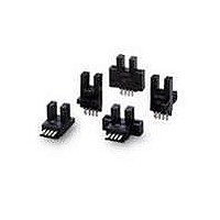
EE-1003 Omron, EE-1003 Datasheet

EE-1003
Specifications of EE-1003
Available stocks
Related parts for EE-1003
EE-1003 Summary of contents
Page 1
... Part number Lens unit E39-F1 Side view lens unit E39-F2 Fiber cutter E39-F4 Connector (solder terminals) EE-1002 Connector with 1 m wire EE-1003 Type Output configuration Fiber-connecting Dark-ON Light-ON Sensing object Directional angle Part number Opaque, 1-mm dia. 5° to 40° Opaque, 4-mm dia. min. ...
Page 2
... Destruction Hz, 1.5-mm double amplitude for 2 hrs each and Z directions 2 Destruction: 500 m/s (approx. 50G’s) for 3 times each and Z directions 5 m max. (AWG24 min.) EE-SPZ401 Light-ON 2 ...
Page 3
... Fiber length Angle θ (°) 3 EE-SPZ301/SPZ401 with E32-TC200 and E39-F1 Vcc = 10 V Fiber length Operating level Distance d (mm) EE-SPZ301/SPZ401 with E32-DC200 d Vcc = 10 V Object: White paper with a reflection factor of 90% Fiber length Operating level Distance d (mm) J RECEIVER OUTPUT VS. BENDING ...
Page 4
... J SENSING POSITION CHARACTERISTICS (TYPICAL) EE-SPZ301/SPZ401 with E32-TC200 Distance Y Vcc = 10 V Fiber length Distance X Size of edge (mm) EE-SPZ301/SPZ401 with E32-TC200 and E39-F2 Vcc = 10 V Fiber length Distance Y Distance X Distance X (mm) EE-SPZ301/SPZ401 with E32-DC200 Distance Y Distance X Vcc Object: White paper 2 (15 x 15mm ) with a reflection factor of 90% ...
Page 5
... Incident Interrupted LIGHT indicator ON (red) OFF Output ON transistor OFF Operates Load (relay) Releases Output voltage H (logic EE-SPZ301/SPZ401 with E32-DC200 VDC 0 V Dark-ON LIGHT indicator (red) Output transistor Load (relay) Output voltage (logic) A fiber length converted into 1. Fiber length (cm) Incident Interrupted ON OFF ...
Page 6
... Two, 3.2, dia. (0.24) holes 3 (0.12) Indicator (1) 1.25(0.05 (0.55) (2) (0.20) 20 2.5(0.10) (0.55) (3) Three, 0.635 x 0.635 terminals 7.4 (0.29) 4.4 (0.17) 3 (0.12 0.7 M2.6 x 0.45 8.5 dia. 2.4 (0.09) 3 0.9 (0.04) 3.2 (0.12) (78.74) 14 (0.55) 3.2 dia 0.75 4 dia. ...
Page 7
... Terminal Arrangement (1) Brown (Red (2) Black (White) OUT OUTPUT (3) Blue (Black) GND (O V) Note: Older standard colors are shown in parentheses. The connector comes with a 1-m attached cable. Note: Use the EE1003A Connector Holder to prevent accidental disconnection of the EE-1003 Connector from the EE-SPZ301/401 Photomicrosensor. ...
Page 8
... Do not solder the cable to the connectors. Use the EE-1002 Connector or EE-1003 Connector (with a 1-m cable attached) to connect the cable to the output terminals. Use the EE1003A Connector Holder to prevent accidental discon- nection of the EE-1003 Connector from the EE-SPZ301/401 Photomicrosensor ...
Page 9
... J INSERTING THE FIBER UNIT Do not pull or push the Fiber Unit with excessive force. Bend the fiber in as large a radius as possible and 25 mm min. Do not bend the portions between the both ends and 40 mm from the ends of the fiber min. Fiber unit Main body 40 mm min ...
Page 10
... Cutter. 2. Push down the blade in one strong, smooth motion. Do not re-use a hole that has been used once to cut a fiber cable. The chances of a cut surface being cut irregularly greatly increase, which would in turn shorten the cable’s sensing distance ...


