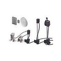
E39-R1 Omron, E39-R1 Datasheet - Page 7

E39-R1
Manufacturer Part Number
E39-R1
Description
Industrial Photoelectric Sensors CORNER CUBE REFLCTR
Manufacturer
Omron
Type
Reflectorr
Specifications of E39-R1
Features
Control the laser with an Amplifier the same size as a Digital Fiber Amplifier
Light Source
Infrared LED
Connection
Prewired Cable
Output Configuration
NPN
Reflector Type
Retro Reflective
Accessory Type
Reflector
For Use With
Retroflective Sensors
Lead Free Status / RoHS Status
Lead free / RoHS Compliant
For Use With/related Products
OR538 and OR539
Lead Free Status / RoHS Status
Lead free / RoHS Compliant, Lead free / RoHS Compliant
Available stocks
Company
Part Number
Manufacturer
Quantity
Price
Company:
Part Number:
E39-R1
Manufacturer:
Omron Electronics
Quantity:
135
* Models numbers for Through-beam Sensors (E3S-AT@1) are for sets that include both the Emitter and Receiver.
Structure of Sensor I/O Connector
E3S-AT21
E3S-AT71
E3S-AD21
E3S-AD71
E3S-AD22
E3S-AD72
E3S-AD23
E3S-AD73
E3S-AR21
E3S-AR71
The model number of the Emitter is expressed by adding "-L" to the set model number (example: E3S-AT21-L 2M), the model number of the Receiver, by adding "-D"
(example: E3S-AT21-D 2M). Refer to Ordering Information to confirm model numbers for Emitter and Receivers.
1
Model
2
4
3
*
*
Terminal No.
1
2
3
4
Operation
Light-ON
Dark-ON
Light-ON
Dark-ON
mode
---
XS2F-D421-DC0-A
Light indicator
(red)
Load
(e.g., relay)
Light indicator
(red)
Load
(e.g., relay)
Light indicator
(red)
Load
(e.g., relay)
Light indicator
(red)
Load
(e.g., relay)
Output
transistor
Output
transistor
Output
transistor
Emitter LED
Output
transistor
T: OFF-delay timer (0 to 100 ms)
No incident light
T: OFF-delay timer (0 to 100 ms)
No incident light
T: OFF-delay timer (0 to 100 ms)
No incident light
No incident light
T: OFF-delay timer (0 to 100 ms)
External
diagnostic
input
Indicator
(red)
Incident light
Incident light
Incident light
Incident light
Timing charts
Operate
Operate
Operate
Operate
Reset
Reset
Reset
Reset
OFF
OFF
OFF
OFF
OFF
OFF
OFF
OFF
OFF
OFF
OFF
ON
ON
ON
ON
ON
ON
ON
ON
ON
ON
ON
(Between brown and black)
(Between brown and black)
(Between brown and black)
(Between brown and black)
(Between blue and pink)
T
T
T
T
Brown
Blue
Black
L Side
(LIGHT ON)
D Side
(DARK ON)
L Side
(LIGHT ON)
D Side
(DARK ON)
selector
Note: Pin No. 2 is not used.
switch
Classification
Mode
---
For DC
Through-beam Receivers, Diffuse-reflective Sensors
Through-beam Emitters
Retro-reflective Sensors
Light
indica-
tor
(red)
Light
indica-
tor
(red)
Wire color
Brown
Black
Blue
Stability
indicator
(green)
Stability
indicator
(green)
---
Photo-
electric
Sensor
main
circuit
Photo-
electric
Sensor
main
circuit
Power indicator
(red)
Photo-
electric
Sensor
main
circuit
Connection Pin No.
Output circuit
Z
Z
D
D
100 mA max.
100 mA max.
50 mA max.
50 mA max.
Z
Brown
Blue
1
2
3
4
Z
Pink
D
D
12 K
10 to 30 VDC
(External
diagnostic input)
Black
Black
Orange
Orange
Blue
Brown
Brown
Blue
Pink
(Control
output)
(Control
output)
(relay)
(relay)
Load
Load
0 V
(Self-diagnostic
output)
(Self-diagnostic
output)
(External
diagnostic input)
Application
(relay)
(relay)
Load
Load
E3S-A
Output
0 V
+V
---
10 to
30 VDC
10 to
30 VDC
7


