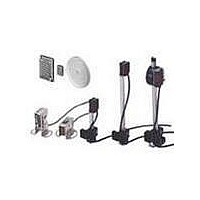
E39-R1 Omron, E39-R1 Datasheet - Page 12

E39-R1
Manufacturer Part Number
E39-R1
Description
Industrial Photoelectric Sensors CORNER CUBE REFLCTR
Manufacturer
Omron
Type
Reflectorr
Specifications of E39-R1
Features
Control the laser with an Amplifier the same size as a Digital Fiber Amplifier
Light Source
Infrared LED
Connection
Prewired Cable
Output Configuration
NPN
Reflector Type
Retro Reflective
Accessory Type
Reflector
For Use With
Retroflective Sensors
Lead Free Status / RoHS Status
Lead free / RoHS Compliant
For Use With/related Products
OR538 and OR539
Lead Free Status / RoHS Status
Lead free / RoHS Compliant, Lead free / RoHS Compliant
Available stocks
Company
Part Number
Manufacturer
Quantity
Price
Company:
Part Number:
E39-R1
Manufacturer:
Omron Electronics
Quantity:
135
Dimensions
E3S-A Built-in Amplifier Photoelectric Sensor
Note: Models numbers for Through-beam Sensors (E3S-AT@1) are for sets that include both the Emitter and Receiver.
E3S-AT11/21/31/41 (Receiver)
A*
*The Mounting Bracket can be attached to side A.
A*
*The Mounting Bracket can be attached to side A.
Through-beam Sensors (Horizontal)
Pre-wired Sensors
E3S-AT21/41(Emitter)
Emitter: E3S-AT@@-L
Receiver: E3S-AT@@-D
E3S-AT11/31 (Emitter)
The model number of the Emitter is expressed by adding "-L" to the set model number (example: E3S-AT11-L 2M), the model number of the Receiver, by adding "-D"
(example: E3S-AT11-D 2M). Refer to Ordering Information to confirm model numbers for Emitter and Receivers.
Optical axis
Optical axis
1.2
1.2 10.7
10.7
28.9
5.5
28.9
5.5
28.9
29.2
With Mounting Bracket Attached
16.9
Optical
axis
29.2
Optical
axis
16.9
With Mounting Bracket Attached
Optical
axis
16.9
10.5
10.5
10.5
5
5
5
20
30
Unless otherwise specified, the tolerance class IT16 is used for dimensions in this data sheet.
30
20
30
20
Two, M3 × 12 screws
Two, M3 × 12 screws
7.2
7.2
7.2
Stainless steel
(SUS304)
Stainless steel
(SUS304)
3.1
3.1
3.1
7.2
7.2
7.2
21
Lens (7 × 7)
21
Lens (7 × 7)
8
8
12.4
Power indicator (red)
Optical axis
12
Sensitivity adjuster (white)
Optical axis
*1. Not applicable to Sensors with timer adjusters (E3S-AT11 and E3S-AT31).
*2. The E3S-AT11 or E3S-AT31 has three conductors.
12.4
12.4
Light indicator
(red)
12.9
10.5
1.3
12
1.3
12
Stability indicator (green)
Mounting Holes
Two, M3 holes
12.9
10.5
12.5
10.5
40
20
20
17.8
Mounting Holes
Timer adjuster (black) *1
Two, M3 holes
Power indicator (red)
Turbo switch
7
40
20
40
20
20
5.5
(4)
Two, M3 × 12 screws
Two, M3 × 12 screws
4-dia. vinyl-insulated round
cable with 3 conductors
(Conductor cross section:
0.2 mm
Insulator diameter: 1.1 mm),
Standard length: 2 m
8.8 dia.
(4)
(4)
Operation mode
selector switch
2
,
4-dia. vinyl-insulated
round cable with
4 conductors
(Conductor cross
section: 0.2 mm
Insulator diameter:
1.1 mm),
Standard length: 2 m *2
4-dia. vinyl-insulated
round cable with
2 conductors
(Conductor cross
section: 0.2 mm
Insulator diameter:
1.1 mm),
Standard length: 2 m
8.8 dia.
E3S-A
8.8 dia.
(Unit: mm)
2
,
2
,
12


