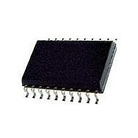
73S8014RN-IL/F Maxim Integrated Products, 73S8014RN-IL/F Datasheet - Page 4

73S8014RN-IL/F
Manufacturer Part Number
73S8014RN-IL/F
Description
IC SMART CARD 7816 EMV 20-SOIC
Manufacturer
Maxim Integrated Products
Datasheet
1.73S8014RN-DB.pdf
(28 pages)
Specifications of 73S8014RN-IL/F
Controller Type
Smart Card Interface
Voltage - Supply
2.7 V ~ 5.5 V
Operating Temperature
-40°C ~ 85°C
Mounting Type
Surface Mount
Package / Case
20-SOIC (0.300", 7.50mm Width) Exposed Pad
Lead Free Status / RoHS Status
Lead free / RoHS Compliant
Current - Supply
-
Interface
-
Lead Free Status / Rohs Status
Lead free / RoHS Compliant
Available stocks
Company
Part Number
Manufacturer
Quantity
Price
Company:
Part Number:
73S8014RN-IL/F
Manufacturer:
Maxim
Quantity:
234
Company:
Part Number:
73S8014RN-IL/F
Manufacturer:
TI
Quantity:
15
Figures
Figure 1: 73S8014RN Block Diagram ....................................................................................................................... 2
Figure 2: 73S8014RN 20-SOP Pin Out ..................................................................................................................... 5
Figure 3: 73S8014RN – Typical Application Schematic .......................................................................................... 14
Figure 4: Activation Sequence – RSTIN Low When CMDVCC Goes Low ............................................................. 16
Figure 5: Activation Sequence – RSTIN High When CMDVCC Goes Low ............................................................. 17
Figure 6: Deactivation Sequence ............................................................................................................................ 18
Figure 7: Timing Diagram – Management of the Interrupt Line OFF ...................................................................... 19
Figure 8: I/O and I/OUC State Diagram................................................................................................................... 20
Figure 9: I/O – I/OUC Delays – Timing Diagram ..................................................................................................... 20
Figure 10: Open Drain type – OFF .......................................................................................................................... 21
Figure 11: Power Input/Output Circuit, V
Figure 12: Type 5 – Smart Card CLK Driver Circuit ................................................................................................ 22
Figure 13: Type 6 – Smart Card RST Driver Circuit ................................................................................................ 22
Figure 14: Type 7A – Smart Card IO Interface Circuit ............................................................................................ 23
Figure 15: Type 7B – Smart Card IOUC Interface Circuit ....................................................................................... 23
Figure 16: Type 8 – General Input Circuit ............................................................................................................... 24
Figure 17: Oscillator Circuit ..................................................................................................................................... 24
Figure 18: VDD
Figure 19: Mechanical Drawing 20-Pin SO Package .............................................................................................. 26
Tables
Table 1: 73S8014RN 20-Pin SOP Pin Definitions ..................................................................................................... 6
Table 2: Absolute Maximum Device Ratings ............................................................................................................. 8
Table 3: Recommended Operating Conditions ......................................................................................................... 8
Table 4: Package Thermal Parameters ..................................................................................................................... 8
Table 5: DC Smart Card Interface Requirements ..................................................................................................... 9
Table 6: Digital Signals Characteristics ................................................................................................................... 11
Table 7: DC Characteristics ..................................................................................................................................... 12
Table 8: Voltage Fault Detection Circuits ................................................................................................................ 12
Table 9: Order Numbers and Packaging Marks ...................................................................................................... 27
4
FLT_ADJ
.............................................................................................................................................. 25
DD
, V
PC
, V
CC
.............................................................................................. 21
Rev. 1.0


