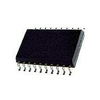
73S8014RN-IL/F Maxim Integrated Products, 73S8014RN-IL/F Datasheet - Page 19

73S8014RN-IL/F
Manufacturer Part Number
73S8014RN-IL/F
Description
IC SMART CARD 7816 EMV 20-SOIC
Manufacturer
Maxim Integrated Products
Datasheet
1.73S8014RN-DB.pdf
(28 pages)
Specifications of 73S8014RN-IL/F
Controller Type
Smart Card Interface
Voltage - Supply
2.7 V ~ 5.5 V
Operating Temperature
-40°C ~ 85°C
Mounting Type
Surface Mount
Package / Case
20-SOIC (0.300", 7.50mm Width) Exposed Pad
Lead Free Status / RoHS Status
Lead free / RoHS Compliant
Current - Supply
-
Interface
-
Lead Free Status / Rohs Status
Lead free / RoHS Compliant
Available stocks
Company
Part Number
Manufacturer
Quantity
Price
Company:
Part Number:
73S8014RN-IL/F
Manufacturer:
Maxim
Quantity:
234
Company:
Part Number:
73S8014RN-IL/F
Manufacturer:
TI
Quantity:
15
3.9 Fault Detection and OFF
There are two different cases that the system controller can monitor the OFF signal: to query regarding the card
presence outside card sessions, or for fault detection during card sessions.
Outside a card session: In this condition, CMDVCC is always high, OFF is low if the card is not present, and high
if the card is present. Because it is outside a card session, any fault detection will not act upon the OFF signal.
No deactivation is required during this time.
During a card session: CMDVCC is always low, and OFF falls low if the card is extracted or if any fault detection
is detected. At the same time that OFF is set low, the sequencer starts the deactivation process.
Figure 7
the card session:
the card session:
3.10 I/O Circuitry and Timing
The state of the I/O pin is low after power on reset and it goes high when the activation sequencer turns on the
I/O reception state. See the
state of I/OUC is high after power on reset.
Within a card session and when the I/O reception state is turned on, the first I/O line on which a falling edge is
detected becomes the input I/O line and the other becomes the output I/O line. When the input I/O line rising
edge is detected then both I/O lines return to their neutral state.
Note: In certain situations and conditions, the I/O logic can get confused if the host and the card attempt to drive
the IOUC and the I/O signal low at the same time. It should be noted that this is an illegal condition as all card
communication is initiated by the host with a command/response protocol. The next host command should not be
sent until a valid response has been completely received from the card. However, if this condition should occur,
the 8014 may set both the IOUC and the I/O as outputs where they are both driven low at the same time. When
either side drives their respective signal high, then this mode should be released. However, if there is a series
resistance between the host and the 8014, then there may not be enough drive to release this mode. If the series
resistance is greater than about 100 ohms, then this may cause this mode to become locked for the duration of
the card session. If the host detects this condition (IOUC held low for more than one byte time), the card session
must be terminated and restarted.
Figure 8
delay between the I/O signals is shown in
Rev. 1.0
shows the timing diagram for the signals CMDVCC, PRES, and OFF during a card session and outside
shows the state diagram of how the I/O and I/OUC lines are managed to become input or output. The
CMDVCC
CMDVCC
VCC
VCC
PRES
PRES
OFF
OFF
Figure 7: Timing Diagram – Management of the Interrupt Line OFF
outside card session
Activation Sequence
Figure
9.
section for details on when the I/O reception is enabled. The
within card session
card extracted
OFF is low by
within card
session
OFF is low by
any fault
e
19


