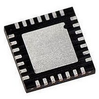
PIC18F24K22-I/ML Microchip Technology, PIC18F24K22-I/ML Datasheet - Page 257

PIC18F24K22-I/ML
Manufacturer Part Number
PIC18F24K22-I/ML
Description
IC PIC MCU 16KB FLASH 28QFN
Manufacturer
Microchip Technology
Series
PIC® XLP™ 18Fr
Datasheets
1.PIC16F722-ISS.pdf
(8 pages)
2.PIC18F26J13-ISS.pdf
(496 pages)
3.PIC18F24K22-ISP.pdf
(494 pages)
Specifications of PIC18F24K22-I/ML
Core Size
8-Bit
Program Memory Size
16KB (8K x 16)
Core Processor
PIC
Speed
64MHz
Connectivity
I²C, SPI, UART/USART
Peripherals
Brown-out Detect/Reset, HLVD, POR, PWM, WDT
Number Of I /o
24
Program Memory Type
FLASH
Eeprom Size
256 x 8
Ram Size
768 x 8
Voltage - Supply (vcc/vdd)
1.8 V ~ 5.5 V
Data Converters
A/D 19x10b
Oscillator Type
Internal
Operating Temperature
-40°C ~ 85°C
Package / Case
28-VQFN Exposed Pad
Controller Family/series
PIC18
No. Of I/o's
25
Eeprom Memory Size
256Byte
Ram Memory Size
768Byte
Cpu Speed
64MHz
No. Of Timers
7
Lead Free Status / RoHS Status
Lead free / RoHS Compliant
Available stocks
Company
Part Number
Manufacturer
Quantity
Price
Company:
Part Number:
PIC18F24K22-I/ML
Manufacturer:
MINI
Quantity:
2 001
Part Number:
PIC18F24K22-I/ML
Manufacturer:
MICROCHIP/微芯
Quantity:
20 000
- Current page: 257 of 496
- Download datasheet (5Mb)
REGISTER 15-2:
2010 Microchip Technology Inc.
bit 3-0
Note 1:
2:
3:
4:
In Master mode, the overflow bit is not set since each new reception (and transmission) is initiated by writing to the
SSPxBUF register.
When enabled, these pins must be properly configured as input or output.
When enabled, the SDAx and SCLx pins must be configured as inputs.
SSPxADD values of 0, 1 or 2 are not supported for I
SSPxM<3:0>: Synchronous Serial Port Mode Select bits
0000 = SPI Master mode, clock = F
0001 = SPI Master mode, clock = F
0010 = SPI Master mode, clock = F
0011 = SPI Master mode, clock = TMR2 output/2
0100 = SPI Slave mode, clock = SCKx pin, SSx pin control enabled
0101 = SPI Slave mode, clock = SCKx pin, SSx pin control disabled, SSx can be used as I/O pin
0110 = I
0111 = I
1000 = I
1001 = Reserved
1010 = SPI Master mode, clock = F
1011 = I
1100 = Reserved
1101 = Reserved
1110 = I
1111 = I
SSPxCON1: SSPx CONTROL REGISTER 1 (CONTINUED)
2
2
2
2
2
2
C Slave mode, 7-bit address
C Slave mode, 10-bit address
C Master mode, clock = F
C firmware controlled Master mode (slave idle)
C Slave mode, 7-bit address with Start and Stop bit interrupts enabled
C Slave mode, 10-bit address with Start and Stop bit interrupts enabled
OSC
OSC
OSC
OSC
OSC
Preliminary
/4
/16
/64
/(4 * (SSPxADD+1))
/ (4 * (SSPxADD+1))
2
C Mode.
PIC18(L)F2X/4XK22
(4)
DS41412D-page 257
Related parts for PIC18F24K22-I/ML
Image
Part Number
Description
Manufacturer
Datasheet
Request
R

Part Number:
Description:
Manufacturer:
Microchip Technology Inc.
Datasheet:

Part Number:
Description:
Manufacturer:
Microchip Technology Inc.
Datasheet:

Part Number:
Description:
Manufacturer:
Microchip Technology Inc.
Datasheet:

Part Number:
Description:
Manufacturer:
Microchip Technology Inc.
Datasheet:

Part Number:
Description:
Manufacturer:
Microchip Technology Inc.
Datasheet:

Part Number:
Description:
Manufacturer:
Microchip Technology Inc.
Datasheet:

Part Number:
Description:
Manufacturer:
Microchip Technology Inc.
Datasheet:

Part Number:
Description:
Manufacturer:
Microchip Technology Inc.
Datasheet:


