D2HW-BL221M Omron, D2HW-BL221M Datasheet - Page 9
D2HW-BL221M
Manufacturer Part Number
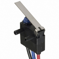
D2HW-BL221M
Description
SWITCH LEVER SPDT 2A SEALED
Manufacturer
Omron
Series
D2HWr
Type
Snap Actionr
Specifications of D2HW-BL221M
Circuit
SPDT
Switch Function
On-Mom
Contact Rating @ Voltage
2A @ 12VDC
Actuator Type
Lever, Straight
Mounting Type
Chassis Mount
Termination Style
Wire Leads
Operating Force
50gf
Contact Form
SPDT
Contact Rating
1 Amp at 24 Volts
Actuator
Lever, Hinge
Post Position
Downwards
Microswitch Type
Ultra Subminiature
Actuator Style
Hinge Lever
Switch Operation
ON-OFF
Operating Force Max
50gf
Contact Voltage Ac Nom
125V
Contact Voltage Dc Nom
42V
Body Style
Subminiature
Brand/series
D2HW Series
Current, Rating
1 A
Dielectric Strength
1500 VAC
Ip Rating
IP67
Mounting Hole Size
2.4 mm
Number Of Poles
1
Number Of Positions
2
Operation
On-Off
Standards
RoHS Compliant
Temperature, Operating
- 40 to + 85 °C
Termination
Lead Wire
Voltage, Rating
24 VDC
Lead Free Status / RoHS Status
Lead free / RoHS Compliant
Lead Free Status / RoHS Status
Lead free / RoHS Compliant, Lead free / RoHS Compliant
Other names
D2HWBL221M
SW736
SW736


D2HW-Aj
Models without Posts
(0.20±0.004)
J MOUNTING STRUCTURE AND REFERENCE POSITIONS
The reference positions used for FP, OP, and TTP values are as shown below for each type of mounting.
J TERMINALS
Reference
position
5.08±0.1
Lead Wires on Left-side
PCB Cutout Dimensions
(Reference)
Straight PCB Terminals
(0.20)
(0.20)
5.08
5
Three, 1
(0.28)
1.7 dia.
(0.07)
7
(11.81±0.39)
(0.20)
5.08
300±10
+0.1
0
dia. hole
(0.20±0.004)
5.08±0.1
(0.52)
13.3
Three-0.6
(0.10)
2.5
(0.16)
4
(0.52)
(0.21)
13.3
5.3
(0.02)
Reference
position
0.5
depth: 5 mm
(0.20 in) min.
2.4
(0.09
(0.24±0.004)
depth: 5 mm
(0.20 in) min.
2.4
(0.09
(0.26)
(0.47)
+0.1
- -0
6±0.1
(0.20±0.004)
6.5
Mounting Hole Dimensions
(Reference)
+0.004
- -0
12
+0.1
- -0
5.08±0.1
+0.004
- -0
)
(0.47)
1.7 dia.
(0.07)
(0.12)
D2HW-Bj
Models with Posts
)
12
3
PCB Cutout Dimensions
(Reference)
(0.31±0.004)
(0.20)
5.08
Angled PCB Terminals
(0.31±0.004)
8±0.1
Lead Wires on Right-side
8±0.1
(0.31±0.004)
(0.20)
5.08
(0.52)
13.3
8±0.1
(0.52)
13.3
Sealed Subminiature Snap Action Switch
(0.20±0.004)
Three-0.6
2.6 dia.
(0.10)
Three, 1
5.08±0.1
2.6 dia.
(0.10)
(0.10±0.002
5
(0.20
2.4
(0.09
2.6±0.06
+0
- -0.2
2.4
(0.09
+0.1
- -0
+0.1
+0
- -0.004
(0.24)
(0.02)
)
+0.004
- -0
0
0.5
6
+0.1
- -0
(11.81±0.39)
dia. hole
+0.004
- -0
)
300±10
)
(0.11)
2.85
(0.21)
)
5.3
(0.20)
Reference
position
5
(0.10)
2.65
Mounting Hole Dimensions
(Reference)
D2HW-Cj
M3-screw Mounting Models
(11.81±0.39)
(0.47)
300±10
12
(0.07)
(0.05)
1.8
1.2
5 (0.20)
(0.17)
(0.51±0.004
4.38
13±0.1
Lead Wires Downwards
(0.51±0.004
(0.73)
18.5
13±0.1
)
Solder Terminals
3
(0.12
depth: 1.5 mm (0.06 in) min.
)
+0.1
0
+0.004
dia.
0
3.3±0.15 dia.
D2HW
(0.13±0.006)
1.5
(0.06
)
(0.17)
3.1
(0.12
M3 tap
4.38
(0.24)
+0
- -0.1
Three-2
+0.13
+0
- -0.004
- -0.03
(0.13)
6
+0.005
- -0.001
3.4
COM AWG20
(Black)
NO AWG20 (Blue)
NC AWG20 (Red)
)
(0.26)
)
6.5
(0.21)
5.3
1.5
(0.06
(0.02)
+0
- -0.1
+0
- -0.004
0.5
7
)
Related parts for D2HW-BL221M
Image
Part Number
Description
Manufacturer
Datasheet
Request
R

Part Number:
Description:
SUBMINIATURE BASIC SWITCH
Manufacturer:
Omron
Datasheet:
Part Number:
Description:
SUBMINIATURE BASIC SWITCH
Manufacturer:
Omron
Datasheet:
Part Number:
Description:
SUBMINIATURE BASIC SWITCH
Manufacturer:
Omron
Datasheet:
Part Number:
Description:
SUBMINIATURE BASIC SWITCH
Manufacturer:
Omron
Datasheet:
Part Number:
Description:
SUBMINIATURE BASIC SWITCH
Manufacturer:
Omron
Datasheet:
Part Number:
Description:
SUBMINIATURE BASIC SWITCH
Manufacturer:
Omron
Datasheet:
Part Number:
Description:
SUBMINIATURE BASIC SWITCH
Manufacturer:
Omron
Datasheet:
Part Number:
Description:
SWITCH SUBMINIATURE BASIC SPDT
Manufacturer:
Omron
Datasheet:
Part Number:
Description:
SWITCH SUBMINIATURE BASIC SPDT
Manufacturer:
Omron
Datasheet:
Part Number:
Description:
SWITCH SUBMINI BASIC SPDT-NO
Manufacturer:
Omron
Datasheet:
Part Number:
Description:
SWITCH SUBMINIATURE BASIC SPDT
Manufacturer:
Omron
Datasheet:
Part Number:
Description:
SWITCH SUBMINI BASIC SPST-NO
Manufacturer:
Omron
Datasheet:

Part Number:
Description:
SWITCH SUBMINI BASIC SPDT-NO
Manufacturer:
Omron
Datasheet:

Part Number:
Description:
SWITCH BASIC SPDT 2A SEALED
Manufacturer:
Omron
Datasheet:

Part Number:
Description:
SWITCH LEVER SPDT 2A SEALED
Manufacturer:
Omron
Datasheet: