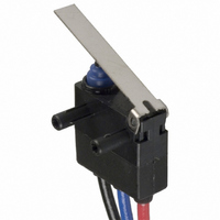
D2HW-BL221M Omron, D2HW-BL221M Datasheet

D2HW-BL221M
Specifications of D2HW-BL221M
SW736
Related parts for D2HW-BL221M
D2HW-BL221M Summary of contents
Page 1
... SPST-NO (Molded lead wire models only.) 5. Terminals D: Straight PCB terminals DR: Right-angled PCB terminals DL: Left-angled PCB terminals H: Solder terminals M: Molded lead wires downwards MR: Molded lead wires on right-side ML: Molded lead wires on left-side Note Add “S” to the end of the model number for the UL/CSA- approved version. D2HW 1 ...
Page 2
... D2HW-BL201M D2HW-C201M D2HW-BL202M D2HW-C202M D2HW-BL203M D2HW-C203M D2HW-BL202MR D2HW-C202MR D2HW-BL203MR D2HW-C203MR D2HW-BL202ML --- D2HW-BL203ML --- D2HW-BL211H D2HW-C211H D2HW-BL211M D2HW-C211M D2HW-BL212M D2HW-C212M D2HW-BL213M D2HW-C213M D2HW-BL212MR D2HW-C212MR D2HW-BL213MR D2HW-C213MR D2HW-BL212ML --- D2HW-BL213ML --- D2HW-BL221H D2HW-C221H D2HW-BL221M D2HW-C221M D2HW-BL222M D2HW-C222M D2HW-BL223M D2HW-C223M D2HW-BL222MR D2HW-C222MR D2HW-BL223MR D2HW-C223MR D2HW-BL222ML --- D2HW-BL223ML --- ...
Page 3
... D2HW-BL233ML --- D2HW-BL241H D2HW-C241H D2HW-BL241M D2HW-C241M D2HW-BL242M D2HW-C242M D2HW-BL243M D2HW-C243M D2HW-BL242MR D2HW-C242MR D2HW-BL243MR D2HW-C243MR D2HW-BL242ML --- D2HW-BL243ML --- D2HW-BL261H D2HW-C261H D2HW-BL261M D2HW-C261M D2HW-BL262M D2HW-C262M D2HW-BL263M D2HW-C263M D2HW-BL262MR D2HW-C262MR D2HW-BL263MR D2HW-C263MR D2HW-BL262ML --- D2HW-BL263ML --- D2HW-BL271H D2HW-C271H D2HW-BL271M D2HW-C271M D2HW-BL272M D2HW-C272M D2HW-BL273M D2HW-C273M D2HW-BL272MR D2HW-C272MR D2HW-BL273MR ...
Page 4
... The equation λ60=035×10−6/operations indicates that a failure rate of 1/2,000,000 operations can be expected at a reliability level of 60%. COM NC (Black) (Red) Item Specification Specification Crossbar Material Gold alloy Gap (standard value) 0 VDC SPST-NO (Molded Lead Wire Models Only) COM NO (Black) (Blue) D2HW ...
Page 5
... PCB Cutout Dimensions (Reference) +0.1 2.4 dia. hole 0 (depth min.) 2.6 +0.1 Three, 1 dia. hole 0 Molded Lead Wires on Right-side (12) (13.3) D2HW 0 3 dia. −0.1 3.3±0.15 dia. +0.1 3 dia. hole 0 (depth: 1.5 mm min.) M3 tap Solder Terminals 3.5 Three-2 Molded Lead Wires Downwards (12) COM AVSS 0 ...
Page 6
... Dimensions not indicated in the above diagrams have a tolerance of ±0.2 mm. 3. The operating characteristics are for operation in the A direction ( Pin Plunger Models D2HW-@20@@ A Hinge Lever Models D2HW-@21@@ A Long Hinge Lever Models D2HW-@22@@ A Simulated Roller Hinge Lever Models D2HW-@23 Model OF max. RF min. 1.7 dia. OT ref. MD max. FP max. OP TTP max ...
Page 7
... D2HW Hinge Roller Lever Models D2HW-@24@@ 4.8 dia. ×2.8 resin roller FP OP TTP 6.5 Leaf Lever Models D2HW-@26@@ Simulated Roller Leaf Lever Models D2HW-@27@@ Long Leaf Lever Models D2HW-@28@@ A (12 8± 0.1 (4.6) 15 t=0.3 stainless steel lever (1.15) 3 (0. 0.3 stainless ...
Page 8
... Otherwise, damage to the Switch or deterioration in the sealing may result. Using Micro Loads Even when using micro load models within the operating range, inrush currents or surges may decrease the life expectancy of the Switch. Therefore, insert a contact protection circuit where neces- sary. D2HW ...


