D2SW-3DS Omron, D2SW-3DS Datasheet - Page 6
D2SW-3DS
Manufacturer Part Number
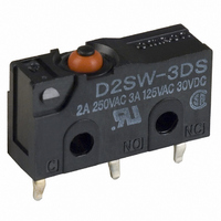
D2SW-3DS
Description
SWITCH 3A BASIC SEALED PC MNT
Manufacturer
Omron
Series
D2SWr
Datasheet
1.D2SW-3TS.pdf
(8 pages)
Specifications of D2SW-3DS
Circuit
SPDT
Switch Function
On-Mom
Contact Rating @ Voltage
3A @ 125VAC
Actuator Type
Round (Pin Plunger)
Mounting Type
Through Hole
Termination Style
PC Pin
Operating Force
180gf
Microswitch Type
Miniature
Actuator Style
Pin Plunger
Operating Force Max
180gf
Contact Voltage Ac Nom
250V
Contact Voltage Dc Nom
30V
Contact Current Max
3A
Contact Form
SPDT
Contact Rating
3 Amps at 125 Volts, 3 Amps at 30 Volts
Actuator
Plunger, Pin
Lead Free Status / RoHS Status
Lead free / RoHS Compliant
Lead Free Status / RoHS Status
Lead free / RoHS Compliant, Lead free / RoHS Compliant
Other names
D2SW-3D
D2SW3DS
SW291
D2SW3DS
SW291


Precautions
Be sure to read the precautions and information common to all Snap Action and Detection Switches, contained in the Technical User’s Guide,
“Snap Action Switches, Technical Information” for correct use.
■ Correct Use
Operation stroke
Make sure that the switching object is perfectly separated from the
actuator when the switch is not operated and the actuator is pressed
appropriately by the switching object when the switch is operated.
The switch should be set so that its stroke will be within the rated OT
when the switch is operated.
Handling
Install the switching object so that its moving direction is the same as
that of the actuator. With the pin plunger models, set the switch so
that the plunger can be actuated from directly above. Since the
plunger is covered with a rubber cap, applying a force from lateral
directions may cause damage to the plunger or reduction in the
sealing capability.
Handle D2SW models with pin plungers with care so that the sealing
rubber parts around the pin plungers will not be damaged.
Make sure that there is no icing when using the D2SW at low
ambient temperatures.
Using Microloads
Using a model for ordinary loads to switch microloads may result in
faulty operation. Instead, use the models that are designed for
microloads and that operate in the following range;
However, even when using microload models within the operating
range shown above, if inrush current or inductive voltage spikes
occur when the contact is opened or closed, then contact wear may
increase and so decrease the service life. Therefore, insert a contact
protection circuit where necessary.
200
Sealed Snap Action Switch
Inoperable
range
Incorrect
Correct
Operating range
for micro load
models D2SW-01
Incorrect
Current (mA)
Operating
range for
general-load
models
D2SW-3
D2SW
■ Cautions
Degree of Protection
The D2SW was tested under water and passed the following water-
tightness test, which however, does not mean that the D2SW can be
used in the water. JIS C0929 (rules for testing the watertightness of
electrical devices and materials), class 7 (watertightness test). Refer
to the following illustration for the test method.
IEC Publication 529, class IP67. Refer to the following illustration for
the test method.
Note: The object to be tested is left in the water for 30 minutes on con-
Protection Against Chemicals
Prevent the switch from coming into contact with oil and chemicals.
Otherwise, damage and deterioration to the switch materials may
occur.
Soldering
When soldering a lead wire to a terminal of the D2SW, use a solder-
ing iron with a maximum capacity of 30 W and do not take more than
5 seconds to solder the lead wire, otherwise the characteristics of the
D2SW may be altered.
dition that the distance between the surface of the water and
the top of the object be 15 cm minimum, and the distance be-
tween the surface of the water and the bottom of the object be
1 m minimum.
Related parts for D2SW-3DS
Image
Part Number
Description
Manufacturer
Datasheet
Request
R

Part Number:
Description:
MINIATURE BASIC SWITCH
Manufacturer:
Omron
Datasheet:
Part Number:
Description:
MINIATURE BASIC SWITCH
Manufacturer:
Omron
Datasheet:

Part Number:
Description:
SWITCH 3A BASIC SEALED SLDR TERM
Manufacturer:
Omron
Datasheet:

Part Number:
Description:
SWITCH 3A LEVER SEALED SLD TERM
Manufacturer:
Omron
Datasheet:

Part Number:
Description:
SWITCH 3A LEVER SEALED SLD TERM
Manufacturer:
Omron
Datasheet:

Part Number:
Description:
SWITCH 3A ROLLER SEALED SLDR
Manufacturer:
Omron
Datasheet:

Part Number:
Description:
SWITCH 3A LEVER SEALED 12"WIRES
Manufacturer:
Omron
Datasheet:

Part Number:
Description:
SWITCH 3A LEVER SEALED 12"WIRES
Manufacturer:
Omron
Datasheet:

Part Number:
Description:
SWITCH 3A ROLLER SEALED 12"WIRES
Manufacturer:
Omron
Datasheet:

Part Number:
Description:
SWITCH 3A BASIC SEALED .110QC
Manufacturer:
Omron
Datasheet:

Part Number:
Description:
SWITCH 3A LEVER SEALED .110QC
Manufacturer:
Omron
Datasheet:

Part Number:
Description:
SWITCH 3A BASIC SEALED 12"WIRES
Manufacturer:
Omron
Datasheet:

Part Number:
Description:
MINIATURE BASIC SWITCH
Manufacturer:
Omron
Datasheet:

Part Number:
Description:
SUBMINIATURE BASIC SWITCH
Manufacturer:
Omron
Datasheet:

Part Number:
Description:
MINIATURE BASIC SWITCH
Manufacturer:
Omron
Datasheet: