DEMOKITCRX14 STMicroelectronics, DEMOKITCRX14 Datasheet - Page 18
DEMOKITCRX14
Manufacturer Part Number
DEMOKITCRX14
Description
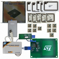
RFID EVALUATION KIT ISO14443-B
Manufacturer
STMicroelectronics
Type
Development kitr
Specifications of DEMOKITCRX14
Contents
CD-ROM, CRX14 Board, USB Transceiver, Samples and Documentation
Processor To Be Evaluated
CRX14
Interface Type
I2C
Operating Supply Voltage
5 V
For Use With/related Products
CRX14
Lead Free Status / RoHS Status
Contains lead / RoHS non-compliant
Other names
497-3704
Available stocks
Company
Part Number
Manufacturer
Quantity
Price
Company:

Part Number:
DEMOKITCRX14
Manufacturer:
HITACHI
Quantity:
340


CRX14 I²C protocol description
4.5
18/47
Figure 6.
I²C memory addressing
To start up communication with the CRX14, the bus master must initiate a START condition.
Then, the bus master sends 8 bits (with the most significant bit first) on the Serial Data line,
SDA. These bits consist of the Device Select Code (7 bits) plus a RW bit.
According to the I²C bus definition, the seven most significant bits of the Device Select Code
are the Device Type Identifier. For the CRX14, these bits are defined as shown in
The 8th bit is the Read/Write bit (RW). It is set to ‘1’ for I²C Read, and to ‘0’ for I²C Write
operations.
If the data sent by the bus master matches the Device Select Code of a CRX14 device, the
corresponding device returns an acknowledgment on the SDA bus during the 9
The CRX14 devices whose Device Select Codes do not correspond to the data sent,
generate a No-ACK. They deselect themselves from the bus and go into stand-by mode.
SCL
SDA
SCL
SDA
SCL
SDA
I²C bus protocol
CONDITION
START
CONDITION
START
MSB
1
MSB
1
2
Doc ID 8880 Rev 4
2
INPUT
SDA
3
3
CHANGE
SDA
7
7
8
8
ACK
9
ACK
CONDITION
9
STOP
CONDITION
STOP
AI00792
th
bit time.
Table
CRX14
6.
Related parts for DEMOKITCRX14
Image
Part Number
Description
Manufacturer
Datasheet
Request
R

Part Number:
Description:
DEMO KIT M24LR-64-R
Manufacturer:
STMicroelectronics
Datasheet:

Part Number:
Description:
STMicroelectronics [RIPPLE-CARRY BINARY COUNTER/DIVIDERS]
Manufacturer:
STMicroelectronics
Datasheet:
Part Number:
Description:
STMicroelectronics [LIQUID-CRYSTAL DISPLAY DRIVERS]
Manufacturer:
STMicroelectronics
Datasheet:

Part Number:
Description:
BOARD EVAL FOR MEMS SENSORS
Manufacturer:
STMicroelectronics
Datasheet:
Part Number:
Description:
NPN TRANSISTOR POWER MODULE
Manufacturer:
STMicroelectronics
Datasheet:
Part Number:
Description:
TURBOSWITCH ULTRA-FAST HIGH VOLTAGE DIODE
Manufacturer:
STMicroelectronics
Datasheet:
Part Number:
Description:
Manufacturer:
STMicroelectronics
Datasheet:
Part Number:
Description:
DIODE / SCR MODULE
Manufacturer:
STMicroelectronics
Datasheet:
Part Number:
Description:
DIODE / SCR MODULE
Manufacturer:
STMicroelectronics
Datasheet:
Part Number:
Description:
Search -----> STE16N100
Manufacturer:
STMicroelectronics
Datasheet:
Part Number:
Description:
Search ---> STE53NA50
Manufacturer:
STMicroelectronics
Datasheet:
Part Number:
Description:
NPN Transistor Power Module
Manufacturer:
STMicroelectronics
Datasheet: