DEMOKITCRX14 STMicroelectronics, DEMOKITCRX14 Datasheet - Page 16
DEMOKITCRX14
Manufacturer Part Number
DEMOKITCRX14
Description
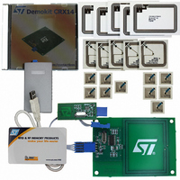
RFID EVALUATION KIT ISO14443-B
Manufacturer
STMicroelectronics
Type
Development kitr
Specifications of DEMOKITCRX14
Contents
CD-ROM, CRX14 Board, USB Transceiver, Samples and Documentation
Processor To Be Evaluated
CRX14
Interface Type
I2C
Operating Supply Voltage
5 V
For Use With/related Products
CRX14
Lead Free Status / RoHS Status
Contains lead / RoHS non-compliant
Other names
497-3704
Available stocks
Company
Part Number
Manufacturer
Quantity
Price
Company:

Part Number:
DEMOKITCRX14
Manufacturer:
HITACHI
Quantity:
340


CRX14 I²C protocol description
4
Table 6.
4.1
16/47
CRX14
Select
CRX14 I²C protocol description
The CRX14 is compatible with the I²C serial bus memory standard, which is a two-wire
serial interface that uses a bi-directional data bus and serial clock.
The CRX14 has a pre-programmed, 4-bit identification code, ’1010’ (as shown in
that corresponds to the I²C bus definition. With this code and the three Chip Enable inputs
(E2, E1, E0) up to eight CRX14 devices can be connected to the I²C bus, and selected
individually.
The CRX14 behaves as a slave device in the I²C protocol, with all CRX14 operations
synchronized to the serial clock.
I²C Read and Write operations are initiated by a START condition, generated by the bus
master.
The START condition is followed by the Device Select Code and by a Read/Write bit (R/W).
It is terminated by an acknowledge bit. The Device Select Code consists of seven bits (as
shown in
●
●
When data is written to the CRX14, the device inserts an acknowledge bit (9th bit) after the
bus master’s 8-bit transmission.
When the bus master reads data, it also acknowledges the receipt of the data Byte by
inserting an acknowledge bit (9th bit).
Data transfers are terminated by a STOP condition after an ACK for Write, or after a NoACK
for Read.
The CRX14 supports the I²C protocol, as summarized in
Any device that sends data on to the bus, is defined as a transmitter, and any device that
reads the data, as a receiver.
The device that controls the data transfer is known as the master, and the other, as the
slave. A data transfer can only be initiated by the master, which also provides the serial
clock for synchronization. The CRX14 is always a slave device in all I²C communications. All
data are transmitted Most Significant Bit (MSB) first.
Device select code
I²C start condition
START is identified by a High-to-Low transition of the Serial Data line, SDA, while the Serial
Clock, SCL, is stable in the High state. A START condition must precede any data transfer
command.
the Device Code (first four bits)
plus three bits corresponding to the states of the three Chip Enable inputs, E2, E1 and
E0, respectively
b7
1
Table
6):
b6
0
Device code
b5
1
Doc ID 8880 Rev 4
b4
0
E2
b3
Figure
Chip enable
E1
b2
6.
E0
b1
Table
RW
RW
CRX14
b0
6),
Related parts for DEMOKITCRX14
Image
Part Number
Description
Manufacturer
Datasheet
Request
R

Part Number:
Description:
DEMO KIT M24LR-64-R
Manufacturer:
STMicroelectronics
Datasheet:

Part Number:
Description:
STMicroelectronics [RIPPLE-CARRY BINARY COUNTER/DIVIDERS]
Manufacturer:
STMicroelectronics
Datasheet:
Part Number:
Description:
STMicroelectronics [LIQUID-CRYSTAL DISPLAY DRIVERS]
Manufacturer:
STMicroelectronics
Datasheet:

Part Number:
Description:
BOARD EVAL FOR MEMS SENSORS
Manufacturer:
STMicroelectronics
Datasheet:
Part Number:
Description:
NPN TRANSISTOR POWER MODULE
Manufacturer:
STMicroelectronics
Datasheet:
Part Number:
Description:
TURBOSWITCH ULTRA-FAST HIGH VOLTAGE DIODE
Manufacturer:
STMicroelectronics
Datasheet:
Part Number:
Description:
Manufacturer:
STMicroelectronics
Datasheet:
Part Number:
Description:
DIODE / SCR MODULE
Manufacturer:
STMicroelectronics
Datasheet:
Part Number:
Description:
DIODE / SCR MODULE
Manufacturer:
STMicroelectronics
Datasheet:
Part Number:
Description:
Search -----> STE16N100
Manufacturer:
STMicroelectronics
Datasheet:
Part Number:
Description:
Search ---> STE53NA50
Manufacturer:
STMicroelectronics
Datasheet:
Part Number:
Description:
NPN Transistor Power Module
Manufacturer:
STMicroelectronics
Datasheet: