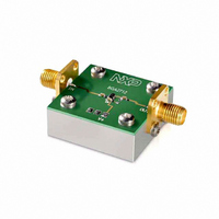
OM7606/BGA2712 NXP Semiconductors, OM7606/BGA2712 Datasheet

OM7606/BGA2712
Specifications of OM7606/BGA2712
Related parts for OM7606/BGA2712
OM7606/BGA2712 Summary of contents
Page 1
DATA SHEET dbook, halfpage BGA2712 MMIC wideband amplifier Product specification Supersedes data of 2002 Jan 31 DISCRETE SEMICONDUCTORS MBD128 2002 Sep 10 ...
Page 2
... NXP Semiconductors MMIC wideband amplifier FEATURES Internally matched to 50 Wide frequency range (3.2 GHz bandwidth) Flat 21 dB gain (DC to 2.6 GHz flatness) 5 dBm saturated output power at 1 GHz Good linearity (11 dBm IP3 (out) Unconditionally stable (K > 1.5). ...
Page 3
... NXP Semiconductors MMIC wideband amplifier THERMAL CHARACTERISTICS SYMBOL PARAMETER R thermal resistance from junction to th j-s solder point CHARACTERISTICS = 25 C; unless otherwise specified 12.3 mA SYMBOL PARAMETER I supply current S s 2 insertion power gain 21 R return losses input return losses output L OUT s ...
Page 4
... NXP Semiconductors MMIC wideband amplifier APPLICATION INFORMATION Figure 2 shows a typical application circuit for the BGA2712 MMIC. The device is internally matched to 50 , and therefore does not need any external matching. The value of the input and output DC blocking capacitors C2 and C3 should not be more than 100 pF for applications above 100 MHz ...
Page 5
... NXP Semiconductors MMIC wideband amplifier handbook, full pagewidth 180° = 30 dBm 12.3 mA handbook, full pagewidth 180° = 30 dBm 12.3 mA 2002 Sep 10 90° +1 135° +0.5 +0.2 100 MHz 0.2 0 GHz −0.2 −0.5 −135° −1 −90° ...
Page 6
... NXP Semiconductors MMIC wideband amplifier 0 handbook, halfpage (dB) −10 −20 −30 −40 −50 0 1000 2000 = 30 dBm 12.3 mA 2 Fig.9 Isolation ( function of frequency; 12 typical values. 10 handbook, halfpage P L (dBm −5 −10 −30 − GHz ( Fig.11 Load power as a function of drive power at 1 GHz ...
Page 7
... NXP Semiconductors MMIC wideband amplifier 6 handbook, halfpage NF (dB) 5 ( 1000 = 50 ( 15 12 10 Fig.13 Noise figure as a function of frequency; typical values. 2002 Sep 10 MLD902 handbook, halfpage (2) 2000 3000 f (MHz Fig.14 Stability factor as a function of frequency 1000 2000 = 50 ...
Page 8
Scattering parameters = 30 dBm 12.3 mA (MHz) MAGNITUDE ANGLE MAGNITUDE (ratio) (deg) 13.48 100 0.04752 200 0.05643 22.73 400 0.09546 ...
Page 9
... NXP Semiconductors MMIC wideband amplifier PACKAGE OUTLINE Plastic surface-mounted package; 6 leads y 6 pin 1 index DIMENSIONS (mm are the original dimensions UNIT max 1.1 0.30 0.25 mm 0.1 0.20 0.8 0.10 OUTLINE VERSION IEC SOT363 2002 Sep scale 2.2 1.35 2.2 1.3 0.65 1.8 1 ...
Page 10
... In no event shall NXP Semiconductors be liable for any indirect, incidental, punitive, special or consequential damages (including - without limitation - lost profits, lost savings, business interruption, costs related to the ...
Page 11
... NXP Semiconductors’ specifications such use shall be solely at customer’s own risk, and (c) customer fully indemnifies NXP Semiconductors for any liability, damages or failed product claims resulting from customer design and use of the product for automotive applications beyond NXP Semiconductors’ ...
Page 12
... Interface, Security and Digital Processing expertise Customer notification This data sheet was changed to reflect the new company name NXP Semiconductors, including new legal definitions and disclaimers. No changes were made to the technical content, except for package outline drawings which were updated to the latest version. ...


