ATAVRRZ200 Atmel, ATAVRRZ200 Datasheet - Page 7
ATAVRRZ200
Manufacturer Part Number
ATAVRRZ200
Description
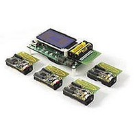
KIT DEMO AT86RF230
Manufacturer
Atmel
Series
AVR®r
Type
802.15.4/Zigbeer
Datasheet
1.ATAVRRZ200.pdf
(25 pages)
Specifications of ATAVRRZ200
Contents
5 Radio Controller Boards, Display Board, ATAVRISP mkII Programming Dongle, and Software
Wireless Frequency
2.45 GHz
For Use With/related Products
AT86RF230
Lead Free Status / RoHS Status
Lead free / RoHS Compliant


2.1
2.2
Demonstration Kit User Guide
Hardware
assembly
Starting and
using the
network
This section provides brief instructions to get the Demonstration kit up and running in
the shortest amount of time. Persons reading this section should be familiar with wire-
less networking; otherwise, read section 3 and section 4 for a full description of the
Demonstration kit. This Demonstration kit is fully self-contained, no external hardware
or software is required to conduct the network demonstration. However, in the event
RCB or Display board reprogramming is desired, a PC is required.
The hardware is assembled by following the steps listed below. Pictures with itemized
callouts are shown in Section 3.
Network device activity is monitored in two places: the network monitor screen and on
the RCBs designated LED units. The following steps describe device monitoring and
the reconfiguration of network devices over the wireless link.
For more detailed information about the following steps, see Section 5, running the
demonstration.
Note:
1. Assemble the five RCBs by inserting two AAA batteries.
2. Assemble the Display Board by inserting two AA batteris at the bottom of the
1. On the Display Board, move the power switch toward the edge of the board
2. When the Atmel splash screen is displayed, move the power switch on the
3. Observe the LCD display indicate channel scan.
4. One at a time, sequentially turn on the four remaining RCBs.
5. Observe as the devices associate with the PAN coordinator (Display) and
6. After all the RCBs are associated, press the SW1 button on the Display
7. Locate the RCBs associated as Switches by checking the MAC address
8. Press SW1 to return to the Configure screen.
board and connecting any RCB.
(BAT).
attached RCB away from the antenna to the ON position.
populate the Configure screen on the LCD.
Board to switch to the network monitor screen.
shown on the Network Monitor screen with the MAC address printed on the
labels attached to each RCB. Observe the LED illumination on an RCB des-
ignated as an LED Unit and also the count increment in the network monitor
screen.
In the following steps, at a minimum, one RCB must be assigned the function of
a Switch Unit and one RCB must be assigned the function of an LED Unit.
Section 2 Getting Started
5183A–ZIGB–12/07/06
2-1
Related parts for ATAVRRZ200
Image
Part Number
Description
Manufacturer
Datasheet
Request
R

Part Number:
Description:
DEV KIT FOR AVR/AVR32
Manufacturer:
Atmel
Datasheet:

Part Number:
Description:
INTERVAL AND WIPE/WASH WIPER CONTROL IC WITH DELAY
Manufacturer:
ATMEL Corporation
Datasheet:
Part Number:
Description:
Low-Voltage Voice-Switched IC for Hands-Free Operation
Manufacturer:
ATMEL Corporation
Datasheet:
Part Number:
Description:
MONOLITHIC INTEGRATED FEATUREPHONE CIRCUIT
Manufacturer:
ATMEL Corporation
Datasheet:
Part Number:
Description:
AM-FM Receiver IC U4255BM-M
Manufacturer:
ATMEL Corporation
Datasheet:
Part Number:
Description:
Monolithic Integrated Feature Phone Circuit
Manufacturer:
ATMEL Corporation
Datasheet:
Part Number:
Description:
Multistandard Video-IF and Quasi Parallel Sound Processing
Manufacturer:
ATMEL Corporation
Datasheet:
Part Number:
Description:
High-performance EE PLD
Manufacturer:
ATMEL Corporation
Datasheet:
Part Number:
Description:
8-bit Flash Microcontroller
Manufacturer:
ATMEL Corporation
Datasheet:
Part Number:
Description:
2-Wire Serial EEPROM
Manufacturer:
ATMEL Corporation
Datasheet: