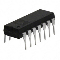
AD713JN Analog Devices Inc, AD713JN Datasheet - Page 11

AD713JN
Manufacturer Part Number
AD713JN
Description
IC OPAMP BIFET QUAD PREC 14DIP
Manufacturer
Analog Devices Inc
Datasheet
1.AD713JRZ-16.pdf
(14 pages)
Specifications of AD713JN
Slew Rate
20 V/µs
Rohs Status
RoHS non-compliant
Amplifier Type
J-FET
Number Of Circuits
4
-3db Bandwidth
4MHz
Current - Input Bias
55pA
Voltage - Input Offset
300µV
Current - Supply
10mA
Current - Output / Channel
25mA
Voltage - Supply, Single/dual (±)
9 V ~ 36 V, ±4.5 V ~ 18 V
Operating Temperature
0°C ~ 70°C
Mounting Type
Through Hole
Package / Case
14-DIP (0.300", 7.62mm)
Op Amp Type
General Purpose
No. Of Amplifiers
4
Bandwidth
4MHz
No. Of Pins
14
Operating Temperature Range
0°C To +70°C
Settling Time
1200ns
Operating Temperature Max
70°C
Output Type
-
Gain Bandwidth Product
-
Lead Free Status / RoHS Status
Contains lead / RoHS non-compliant
Available stocks
Company
Part Number
Manufacturer
Quantity
Price
Part Number:
AD713JN
Manufacturer:
ADI/亚德诺
Quantity:
20 000
Company:
Part Number:
AD713JNZ
Manufacturer:
Analog Devices Inc
Quantity:
1 797
Part Number:
AD713JNZ
Manufacturer:
ADI/亚德诺
Quantity:
20 000
FILTER APPLICATIONS
A Programmable State Variable Filter
For the state variable or universal filter configuration of Figure
18 to function properly, DACs A1 and B1 need to control the
gain and Q of the filter characteristic, while DACs A2 and B2
must accurately track for the simple expression of f
This is readily accomplished using two AD7528 DACs and one
AD713 quad op amp. Capacitor C3 compensates for the effects
of op amp gain-bandwidth limitations.
This filter provides low pass, high pass and band pass outputs
and is ideally suited for applications where microprocessor
control of filter parameters is required. The programmable
range for component values shown is f
Q = 0.3 to 4.5.
GIC and FDNR FILTER APPLICATIONS
The closely matched and uniform ac characteristics of the
AD713 make it ideal for use in GIC (gyrator) and FDNR (fre-
quency dependent negative resistor) filter applications. Figures
C
= 0 to 15 kHz and
C
to be true.
19 and 21 show the AD713 used in two typical active filters.
The first shows a single AD713 simulating two coupled inductors
configured as a one-third octave bandpass filter. A single section
of this filter meets ANSI class II specifications and handles a
7.07 V rms signal with <0.002% THD (20 Hz–20 kHz).
Figure 21 shows a 7-pole antialiasing filter for a 2
pling (88.2 kHz) digital audio application. This filter has <0.05
dB pass band ripple and 19.8 0.3 s delay, dc-20 kHz and will
handle a 5 V rms signal (V
internal nodes.
The filter of Figure 19 can be scaled for any center frequency by
using the formula:
where all resistors and capacitors scale equally. Resistors R3–R8
should not be greater than 2 k in value, to prevent parasitic
oscillations caused by the amplifier’s input capacitance.
S
f
C
= 15 V) with no overload at any
2 RC
1.11
AD713
oversam-


