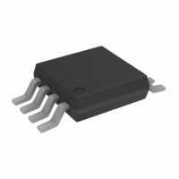
AD8130ARM Analog Devices Inc, AD8130ARM Datasheet - Page 36

AD8130ARM
Manufacturer Part Number
AD8130ARM
Description
IC AMP DIFF LN LDIST 40MA 8MSOP
Manufacturer
Analog Devices Inc
Type
Diff Receiverr
Datasheet
1.AD8129ARZ.pdf
(40 pages)
Specifications of AD8130ARM
Slew Rate
1100 V/µs
Mounting Type
Surface Mount
Rohs Status
RoHS non-compliant
Design Resources
High CMRR Circuit for Converting Wideband Complementary DAC Outputs to Single-Ended Without Precision Resistors (CN0142)
Amplifier Type
Differential
Number Of Circuits
1
-3db Bandwidth
290MHz
Current - Input Bias
500nA
Voltage - Input Offset
400µV
Current - Supply
13mA
Current - Output / Channel
40mA
Voltage - Supply, Single/dual (±)
4.5 V ~ 25.2 V, ±2.25 V ~ 12.6 V
Operating Temperature
-40°C ~ 85°C
Package / Case
8-MSOP, Micro8™, 8-uMAX, 8-uSOP,
No. Of Amplifiers
1
Bandwidth
270MHz
No. Of Pins
8
Settling Time
20ns
Operating Temperature Max
85°C
Peak Reflow Compatible (260 C)
No
Number Of Channels
1
Number Of Elements
1
Power Supply Requirement
Single/Dual
Common Mode Rejection Ratio
86dB
Voltage Gain Db
71dB
Unity Gain Bandwidth Product (typ)
110MHz
Input Resistance
6@5VMohm
Input Offset Voltage
1.8@5VmV
Input Bias Current
2@5VnA
Single Supply Voltage (typ)
5/9/12/15/18/24V
Dual Supply Voltage (typ)
±3/±5/±9/±12V
Rail/rail I/o Type
No
Single Supply Voltage (min)
4.5V
Single Supply Voltage (max)
25.2V
Dual Supply Voltage (min)
±2.25V
Dual Supply Voltage (max)
±12.6V
Operating Temp Range
-40C to 125C
Operating Temperature Classification
Automotive
Mounting
Surface Mount
Pin Count
8
Package Type
MSOP
Output Type
-
Gain Bandwidth Product
-
Lead Free Status / Rohs Status
Not Compliant
Available stocks
Company
Part Number
Manufacturer
Quantity
Price
Part Number:
AD8130ARM
Manufacturer:
ADI/亚德诺
Quantity:
20 000
Company:
Part Number:
AD8130ARM-REEL7
Manufacturer:
AD
Quantity:
5 510
Company:
Part Number:
AD8130ARM-REEL7
Manufacturer:
PANASONIC
Quantity:
5 510
Company:
Part Number:
AD8130ARMZ
Manufacturer:
Analog Devices Inc
Quantity:
135
Part Number:
AD8130ARMZ
Manufacturer:
ADI/亚德诺
Quantity:
20 000
Company:
Part Number:
AD8130ARMZ-REEL7
Manufacturer:
AD
Quantity:
11 492
AD8129/AD8130
Such a connection, also referred to as a cable-tap amplifier, can
be simply made with an AD8130 (see Figure 143). The circuit is
configured with unity gain, and if no output offset is desired,
the REF pin is grounded. The negative differential input is
connected directly to the shield of the cable (or an associated
connector) at the point at which it wants to be tapped.
The center conductor connects to the positive differential input
of the AD8130. The amplitude of the video signal at this point is
unity, because it is between the two termination resistors. The
AD8130 provides a high impedance to this signal so that the
signal is not disturbed. A buffered unity-gain version of the
video signal appears at the output.
POWER-DOWN
The AD8129/AD8130 have a power-down pin that can be used
to lower the quiescent current when the amplifier is not being
used. A logic low level on the PD pin causes the part to power
down. Because there is no ground pin on the AD8129/AD8130,
there is no logic reference to interface to standard logic levels.
For this reason, the reference level for the PD input is V
the AD8129/AD8130 are run with V
compatibility with logic families. However, if V
this, a level-shift circuit is needed to interface to conventional
logic levels. A simple level-shifting circuit that is compatible
with common logic families is presented in Figure 144.
Figure 143. The AD8130 Can Tap the Video Signal at Any Point Along the
Figure 144. Circuit that Shifts the Logic Level When V
VIDEO
IN
POWER-DOWN
75 Ω
LOW =
AD8130
Cable Without Loading the Signal.
75 Ω
Approximately 5 V.
1
8
4
5
4.99k Ω
+
+
1k Ω
PD
3
–V
–V
2
2N2222
OR EQ
S
+V
+V
S
7
S
= 5 V, there is direct
6
0.1 μ F
3 PD
AD8129/
0.1 μ F
AD8130
+V
+V
V
7
S
S
S
OUT
10 μ F
S
is higher than
Is Not Equal to
10 μ F
S
. If
Rev. C | Page 36 of 40
EXTREME OPERATING CONDITIONS
The AD8129/AD8130 are designed to provide high
performance over a wide range of supply voltages. However,
there are some extremes of operating conditions that have
been observed to produce suboptimal results. One of these
conditions occurs when the AD8130 is operated at unity gain
with low supply voltage—less than approximately ±4 V.
At unity gain, the output drives FB directly. With supplies of
±V
drive FB’s voltage too close to the rail for the circuit to stay
properly biased. This can lead to a parasitic oscillation.
A way to prevent this is to limit the input signal swing with
clamp diodes. Common silicon-junction signal diodes like the
1N4148 have a forward bias of approximately 0.7 V when about
1 mA of current flows through them. Two series pairs of such
diodes connected antiparallel across the differential inputs can
be used to clamp the input signal and prevent this condition. It
should be noted that the REF input can also shift the output
signal; therefore, this technique only works when REF is at
ground or close to it (see Figure 145).
Figure 145. Clamping Diodes at the Input Limits the Input Swing Amplitude
S
less than approximately ±4 V at unity gain, the output can
V
V
IN
IN
1N4148
AD8130
8
4
5
1
+
+
PD
3
–V
–V
2
S
+V
+V
7
S
6
0.1 μ F
0.1 μ F
V
OUT
10 μ F
10 μ F


