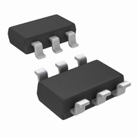
LMV791MK/NOPB National Semiconductor, LMV791MK/NOPB Datasheet - Page 16

LMV791MK/NOPB
Manufacturer Part Number
LMV791MK/NOPB
Description
IC OP AMP CMOS 1.8V TSOT23-6
Manufacturer
National Semiconductor
Series
PowerWise®r
Datasheet
1.LMV792MMNOPB.pdf
(22 pages)
Specifications of LMV791MK/NOPB
Amplifier Type
General Purpose
Number Of Circuits
1
Output Type
Rail-to-Rail
Slew Rate
11.5 V/µs
Gain Bandwidth Product
17MHz
Current - Input Bias
0.1pA
Voltage - Input Offset
100µV
Current - Supply
1.15mA
Current - Output / Channel
60mA
Voltage - Supply, Single/dual (±)
1.8 V ~ 5.5 V
Operating Temperature
-40°C ~ 125°C
Mounting Type
Surface Mount
Package / Case
TSOT-23-6, TSOT-6
Lead Free Status / RoHS Status
Lead free / RoHS Compliant
-3db Bandwidth
-
Other names
LMV791MK
LMV791MKNOPB
LMV791MKNOPBTR
LMV791MKNOPBTR
LMV791MKTR
LMV791MKNOPB
LMV791MKNOPBTR
LMV791MKNOPBTR
LMV791MKTR
www.national.com
AUDIO PREAMPLIFIER WITH BANDPASS FILTERING
With low input referred voltage noise, low supply voltage and
low supply current, and a low harmonic distortion, the
LMV791 family is ideal for audio applications. Its wide unity
gain bandwidth allows it to provide large gain for a wide range
of frequencies and it can be used to design a preamplifier to
drive a load of as low as 600Ω with less than 0.01% distortion.
Two amplifier circuits are shown in Figure 5 and Figure 6.
Figure 5 is an inverting amplifier, with a 10 kΩ feedback re-
sistor, R
gain of −10. Figure 6 is a non-inverting amplifier, using the
same values of R
of these circuits, the coupling capacitor C
frequency at which the circuit starts providing gain, while the
feedback capacitor C
gain starts dropping off. Figure 7 shows the frequency re-
sponse of the inverting amplifier with different values of C
FIGURE 6. Non-inverting Audio Preamplifier
2
, and a 1kΩ input resistor, R
FIGURE 5. Inverting Audio Preamplifier
1
and R
F
decides the frequency at which the
2
, and provides a gain of 11. In either
1
, and hence provides a
C1
decides the lower
20116866
20116865
F
.
16
TRANSIMPEDANCE AMPLIFIER
CMOS input op amps are often used in transimpedance ap-
plications as they have an extremely high input impedance.
A transimpedance amplifier converts a small input current into
a voltage. This current is usually generated by a photodiode.
The transimpedance gain, measured as the ratio of the output
voltage to the input current, is expected to be large and wide-
band. Since the circuit deals with currents in the range of a
few nA, low noise performance is essential. The LMV791/
LMV792 are CMOS input op amps providing wide bandwidth
and low noise performance, and are hence ideal for tran-
simpedance applications.
Usually, a transimpedance amplifier is designed on the basis
of the current source driving the input. A photodiode is a very
common capacitive current source, which requires tran-
simpedance gain for transforming its miniscule current into
easily detectable voltages. The photodiode and amplifier’s
gain are selected with respect to the speed and accuracy re-
quired of the circuit. A faster circuit would require a photodi-
ode with lesser capacitance and a faster amplifier. A more
sensitive circuit would require a sensitive photodiode and a
high gain. A typical transimpedance amplifier is shown in Fig-
ure 8. The output voltage of the amplifier is given by the
equation V
is limited, R
of I
The LMV791/LMV792 have a large gain-bandwidth product
(17 MHz), which enables high gains at wide bandwidths. A
rail-to-rail output swing at 5.5V supply allows detection and
amplification of a wide range of input currents. A CMOS input
stage with negligible input current noise and low input voltage
noise allows the LMV791/LMV792 to provide high fidelity am-
plification for wide bandwidths. These properties make the
LMV791/LMV792 ideal for systems requiring wide-band tran-
simpedance amplification.
FIGURE 7. Frequency Response of the Inverting Audio
IN
can be detected.
OUT
F
should be selected such that all possible values
= −I
IN
R
F
. Since the output swing of the amplifier
Preamplifier
20116858


