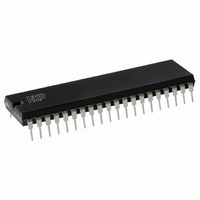
P87C51RC2BN,112 NXP Semiconductors, P87C51RC2BN,112 Datasheet - Page 20

P87C51RC2BN,112
Manufacturer Part Number
P87C51RC2BN,112
Description
IC 80C51 MCU 512 RAM 40DIP
Manufacturer
NXP Semiconductors
Series
87Cr
Datasheet
1.P87C51RC2FA512.pdf
(67 pages)
Specifications of P87C51RC2BN,112
Core Processor
8051
Core Size
8-Bit
Speed
33MHz
Connectivity
EBI/EMI, UART/USART
Peripherals
POR, PWM, WDT
Number Of I /o
32
Program Memory Size
32KB (32K x 8)
Program Memory Type
OTP
Ram Size
512 x 8
Voltage - Supply (vcc/vdd)
2.7 V ~ 5.5 V
Oscillator Type
Internal
Operating Temperature
0°C ~ 70°C
Package / Case
40-DIP (0.600", 15.24mm)
Cpu Family
87C
Device Core
80C51
Device Core Size
8b
Frequency (max)
33MHz
Interface Type
UART
Total Internal Ram Size
512Byte
# I/os (max)
32
Number Of Timers - General Purpose
3
Operating Supply Voltage (typ)
3.3/5V
Operating Supply Voltage (max)
5.5V
Operating Supply Voltage (min)
2.7V
Instruction Set Architecture
CISC
Operating Temp Range
0C to 70C
Operating Temperature Classification
Commercial
Mounting
Through Hole
Pin Count
40
Package Type
PDIP
Processor Series
P87C5x
Core
80C51
Data Bus Width
8 bit
Maximum Clock Frequency
16 MHz
Operating Supply Voltage
2.7 V to 5.5 V
Maximum Operating Temperature
+ 70 C
Mounting Style
SMD/SMT
3rd Party Development Tools
PK51, CA51, A51, ULINK2
Minimum Operating Temperature
0 C
For Use With
OM10064 - EMULATOR 80C51 PDS51-MK2
Lead Free Status / RoHS Status
Lead free / RoHS Compliant
Eeprom Size
-
Data Converters
-
Lead Free Status / Rohs Status
Compliant
Other names
935272150112
P87C51RC2BN
P87C51RC2BN
P87C51RC2BN
P87C51RC2BN
When Timer 2 is in the baud rate generator mode, one should not try
1. Capture/reload occurs only on timer/counter overflow.
2. Capture/reload occurs on timer/counter overflow and a 1-to-0 transition on T2EX (P1.1) pin except when Timer 2 is used in the baud rate
Philips Semiconductors
to read or write TH2 and TL2. As a baud rate generator, Timer 2 is
incremented every state time (osc/2) or asynchronously from pin T2;
under these conditions, a read or write of TH2 or TL2 may not be
accurate. The RCAP2 registers may be read, but should not be
written to, because a write might overlap a reload and cause write
and/or reload errors. The timer should be turned off (clear TR2)
before accessing the Timer 2 or RCAP2 registers.
Table 4 shows commonly used baud rates and how they can be
obtained from Timer 2.
Summary of Baud Rate Equations
Timer 2 is in baud rate generating mode. If Timer 2 is being clocked
through pin T2 (P1.0) the baud rate is:
Table 5.
Table 6.
NOTES:
2003 Jan 24
80C51 8-bit microcontroller family
with 512B/1KB RAM, low voltage (2.7 to 5.5 V), low power, high
speed (30/33 MHz)
16-bit Auto-Reload
16-bit Capture
Baud rate generator receive and transmit same baud rate
Receive only
Transmit only
16-bit
Auto-Reload
generator mode.
Baud Rate + Timer 2 Overflow Rate
Timer 2 as a Timer
Timer 2 as a Counter
16
MODE
MODE
8KB/16KB/32KB/64KB OTP
20
Except for the baud rate generator mode, the values given for T2CON
If Timer 2 is being clocked internally, the baud rate is:
Where f
To obtain the reload value for RCAP2H and RCAP2L, the above
equation can be rewritten as:
Timer/Counter 2 Set-up
do not include the setting of the TR2 bit. Therefore, bit TR2 must be
set, separately, to turn the timer on. see Table 5 for set-up of Timer 2
as a timer. Also see Table 6 for set-up of Timer 2 as a counter.
INTERNAL CONTROL
INTERNAL CONTROL
Baud Rate +
RCAP2H, RCAP2L + 65536 *
(Note 1)
(Note 1)
OSC
00H
01H
34H
24H
14H
02H
03H
= Oscillator Frequency
P87C51RA2/RB2/RC2/RD2
[ n *
* n =
[65536 * (RCAP2H, RCAP2L)]]
T2CON
TMOD
16 in 6-clock mode
32 in 12-clock mode
f
OSC
EXTERNAL CONTROL
EXTERNAL CONTROL
n *
Baud Rate
f
OSC
(Note 2)
(Note 2)
0AH
0BH
08H
09H
36H
26H
16H
Product data


