ST125C506MAJ10 AVX Corporation, ST125C506MAJ10 Datasheet - Page 114
ST125C506MAJ10
Manufacturer Part Number
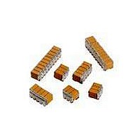
ST125C506MAJ10
Description
CAP CER 50UF 50V STACKED SMD
Manufacturer
AVX Corporation
Series
TurboCap™r
Specifications of ST125C506MAJ10
Capacitance
50µF
Tolerance
±20%
Temperature Coefficient
X7R
Voltage - Rated
50V
Mounting Type
Surface Mount, MLCC
Operating Temperature
-55°C ~ 125°C
Features
Stacked
Applications
Filtering Switch Mode Power Supplies
Package / Case
20-Stacked SMD, J-Lead
Size / Dimension
1.050" L x 0.250" W (26.67mm x 6.35mm)
Thickness
3.56mm Max
Lead Style
J-Lead
Voltage Rating
50 Volts
Operating Temperature Range
- 55 C to + 125 C
Product
General Type MLCCs
Dielectric Characteristic
X7R
Capacitance Tolerance
± 20%
Capacitor Case Style
DIP
No. Of Pins
20
Capacitor Mounting
SMD
Rohs Compliant
No
Termination Style
Radial
Lead Spacing
5.08 mm
Dimensions
6.35 mm W x 26.67 mm L x 3.56 mm H
Dissipation Factor Df
2.5
Lead Free Status / RoHS Status
Contains lead / RoHS non-compliant
Ratings
-
Lead Spacing
-
Lead Free Status / RoHS Status
Contains lead / RoHS non-compliant
Other names
478-6110


Discoidal MLC
Feed-Through Capacitors and Filters
DC Style (US Preferred Sizes) / XB Style (European Preferred Sizes)
XF Style (Feed-Through Discoidal)
APPLICATION INFORMATION ON DISCOIDAL
For dimensions, voltages or values not specified, please consult factory.
ELECTRICAL SPECIFICATIONS
Temperature Coefficient
C0G: A Temperature Coefficient - 0 ±30 ppm/°C, -55° +125°C
X7R: C Temperature Coefficient - ±15%, -55° to +125°C
Z5U: E Temperature Coefficient - +22, -56%, +10° to +85°C
Capacitance Test (MIL-STD-202 Method 305)
C0G: 25°C, 1.0±0.2 Vrms at 1KHz, for ≤100 pF use 1 MHz
X7R: 25°C, 1.0±0.2 Vrms at 1KHz
Z5U: 25°C, 0.5 Vrms max at 1KHz
Dissipation Factor 25°C
C0G: 0.15% Max @ 25°C, 1.0±0.2 Vrms at 1KHz, for ≤100 pF use 1 MHz
X7R: 2.5% Max @ 25°C, 1.0±0.2 Vrms at 1KHz
Z5U: 3.0% Max @ 25°C, 0.5 Vrms max at 1KHz
Insulation Resistance 25°C (MIL-STD-202 Method 302)
C0G and X7R: 100K MΩ or 1000 MΩ-μF, whichever is less.
Z5U: 10K MΩ or 1000 MΩ-μF, whichever is less.
HOW TO ORDER
*Tol. = .254 (0.010) or 3%, whichever is greater
See Pages 100V = 1
DC61
114-116
Style
AVX
+
-
OD*
ID
200V = 2
500V = 7
50V = 5
Voltage Temperature
These surfaces are metallized
.127 (0.005). minimum wide except
for DC61, DC26 and DC63
where metallized surfaces
are .127 (0.005) maximum.
5
T Max.
Coefficient
C0G = A
X7R = C
Z5U = E
A
Capacitance Code
220,000 pF = 224
(2 significant digits
22,000 pF = 223
+ no. of zeros)
1,000 pF = 102
100 pF = 101
Examples:
10 pF = 100
AVX’s DC Series 50V, 100V, 200V, C0G
and X7R parts are capable of meeting
the requirements of MIL-PRF-31033.
LOWEST CAPACITANCE IMPEDANCES TO GROUND
A discoidal MLC capacitor has very low impedance associated with its ground path
since the signal is presented with a multi-directional path. These electrode paths,
which can be as many as 100, allow for low ESR and ESL which are the major ele-
ments in impedance at high frequencies.
The assembled discoidal element or feed-thru allows signal to be fed in through a
chassis or bulkhead, conditioned as it passes through the discoidal, and isolated by
the chassis and discoidal from the original signal. An example of this application
would be in an AFT circuit where the AC noise signal would be required to be
stripped from the DC control signal. Other applications include single line EMI/RFI
suppression, L-C filter construction, and coaxial shield bypass filtering.
The shape of the discoidal lends itself to filter construction. The short length allows
compact construction where L-C construction is desired.
The size freedom associated with this element allows almost any inside/
outside diameter combination. By allowing the inside diameter to equal
the center insulator diameter of a coaxial signal line and special termination tech-
niques, this device will allow bypass filtering of a floating shield to ground.
Discoidal capacitors are available in three temperature coefficients (C0G, X7R, Z5U)
and a variety of sizes, the most standard of which appear in this catalog.
561
1 μF = 105
C0G: J = ±5%
X7R: K = ±10%
Z5U: M = ±20%
Capacitance
Tolerance
M = ±20%
M = ±20%
K = ±10%
P = GMV
Z = +80 -20%
K
Insulation Resistance 125°C (MIL-STD-202 Method 302)
C0G and X7R: 10K MΩ or 100 MΩ-μF, whichever is less.
Z5U: 1K MΩ or 100 MΩ-μF, whichever is less.
Dielectric Withstanding Voltage 25°C (Flash Test)*
C0G and X7R: 250% rated voltage for 5 seconds with 50 mA max
Z5U: 200% rated voltage for 5 seconds with 50 mA max charging current.
Life Test (1000 hrs)
C0G and X7R: 200% rated voltage at +125°C (500 Volt units
Z5U: 150% rated voltage at +85°C
Moisture Resistance (MIL-STD-202 Method 106)
C0G, X7R, Z5U: Ten cycles with no voltage applied.
Thermal Shock (MIL-STD-202 Method 107, Condition A)
Immersion Cycling (MIL-STD-202 Method 104, Condition B)
charging current. 500V rated units will be tested at 750 VDC
@ 600 VDC)
A = Standard
Level
Test
A
(AVX Standard)
Termination
5 = Silver
5
-10
-20
-30
-40
-50
-60
-70
-80
0
0
See Pages 06 = 1.52 (0.060)
Diameter
114-116
100
Inside
200
1
INSERTION LOSS
300
400
f (MHz)
10 = 2.54 (0.100)
500
600
Maximum
Thickness
700
SINGLE CHIP
DISCOIDAL
06
800
900
113
1000
Related parts for ST125C506MAJ10
Image
Part Number
Description
Manufacturer
Datasheet
Request
R

Part Number:
Description:
Manufacturer:
AVX Corporation
Datasheet:
Part Number:
Description:
Manufacturer:
AVX Corporation
Datasheet:
Part Number:
Description:
Manufacturer:
AVX Corporation
Datasheet:
Part Number:
Description:
Manufacturer:
AVX Corporation
Datasheet:
Part Number:
Description:
Manufacturer:
AVX Corporation
Datasheet: