DE2F3KH103MA3B Murata Electronics North America, DE2F3KH103MA3B Datasheet - Page 3
DE2F3KH103MA3B
Manufacturer Part Number
DE2F3KH103MA3B
Description
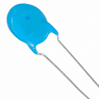
CAP 10000PF 250VAC F X1Y2 RAD
Manufacturer
Murata Electronics North America
Series
KHr
Datasheets
1.DEBB33A681KA2B.pdf
(72 pages)
2.DE2B3KY221KA2BM01.pdf
(1 pages)
3.DE2B3KY221KA2BM01.pdf
(4 pages)
Specifications of DE2F3KH103MA3B
Capacitance
10000pF
Voltage - Rated
250VAC
Tolerance
±20%
Temperature Coefficient
F
Mounting Type
Through Hole
Operating Temperature
-25°C ~ 85°C
Applications
Safety
Ratings
X1Y2
Package / Case
Radial - Disc
Size / Dimension
0.630" Dia (16mm)
Thickness
7.00mm Max
Lead Spacing
0.295" (7.50mm)
Lead Style
Straight
Lead Free Status / RoHS Status
Lead free / RoHS Compliant
Features
-
Other names
490-4217


No.
14 Life
15 Flame Test
16
17 Active Flammability
*
Safety Standard Certified Type KY/KH/KX Specifications and Test Methods
2
"room condition" Temperature: 15 to 35 C, Relative humidity: 45 to 75%, Atmospheric pressure: 86 to 106kPa
Continued from the preceding page.
Robustness
of
Terminations
Item
Appearance
Capacitance
Change
I.R.
Dielectric
Strength
Tensile
Bending
No marked defect
Within 20%
3000M min.
Per Item 6
The capacitor flame discontinues as follows.
Lead wire should not be cut off. Capacitor should
not be broken.
The cheese-cloth should not be on fire.
Cycle
1 to 4
5
Specifications
Time (sec.)
30 max.
60 max.
Impulse Voltage
Each individual capacitor should be subjected to a 5kV (Type
KX: 8kV) impulses for three times. Then the capacitors are
applied to life test.
Apply a voltage of Table 4 for 1000 hrs. at 125+2/-0 C, and
relative humidity of 50% max.
Post-treatment:
The capacitor should be subjected to applied flame for 15 sec.
and then removed for 15 sec. until 5 cycles are completed.
As shown in the figure at right, fix the body
of the capacitor and apply a tensile weight
gradually to each lead wire in the radial
direction of the capacitor up to 10N and keep
it for 10 1 sec.
Each lead wire should be subjected to 5N weight and then a
90 bend, at the point of egress, in one direction, return to
original position, and then apply a 90 bend in the opposite
direction at the rate of one bend in 2 to 3 sec.
The capacitor should be individually wrapped in at least one but
not more than two complete layers of cheesecloth. The
capacitor should be subjected to 20 discharges. The interval
between successive discharges should be 5 sec. The U
should be maintained for 2 min. after the last discharge.
C
L
C
C
F
1 to 4
1,2
t
x
Capacitor should be stored for 1 to 2 hrs. at room condition*
0
100 (%)
90
50
30
AC425V(r.m.s.), except that once each hour the voltage
is increased to AC1000V(r.m.s.) for 0.1 sec.
S
: 1 F 10%
: 1.5mH 20% 16A Rod core choke
: 3 F 5% 10kV
: Capacitor under test
: Fuse, Rated 10A
1
Tr
T
T
1
T
2
S
2
U
U
AC
C
F
x
1
5kV
L
L
Applied Voltage
1
C
3
Gas Burner: Inside Dia. 9.5
Test Method
2
<Table 4>
t
L
L
C
Continued on the following page.
2
4
Front time (T
Time to half-value (T
Capacitor
3
C
R
U
U
U
3
AC
R
t
Flame
C
x
: 0.033 F 5% 10kV
: 100
: U
: Rated Voltage
: Voltage applied to C
time
R
Oscilloscope
1
R
C
) =1.2 s=1.67T
5%
t
W
2%
(in mm)
2
) =50 s
AC
U
t
2
.
t
Related parts for DE2F3KH103MA3B
Image
Part Number
Description
Manufacturer
Datasheet
Request
R

Part Number:
Description:
BUZZER PIEZO 25VP-P SMD
Manufacturer:
Murata Electronics North America

Part Number:
Description:
CAP 4-ARRAY 680PF 100V X7R 1206
Manufacturer:
Murata Electronics North America
Datasheet:
Part Number:
Description:
CAP 4-ARRAY 1000PF 100V X7R 1206
Manufacturer:
Murata Electronics North America
Datasheet:
Part Number:
Description:
CAP 4-ARRAY 1800PF 100V X7R 1206
Manufacturer:
Murata Electronics North America
Datasheet:
Part Number:
Description:
CAP 4-ARRAY 68000PF 16V X7R 1206
Manufacturer:
Murata Electronics North America
Datasheet:

Part Number:
Description:
CAP CER 1000PF 50V 10% X7R 0402
Manufacturer:
Murata Electronics North America
Datasheet:
Part Number:
Description:
CAP CER 10000PF 16V 10% X7R 0402
Manufacturer:
Murata Electronics North America
Datasheet:

Part Number:
Description:
CAP 5.5-25PF 2.5X3.2MM SMD
Manufacturer:
Murata Electronics North America
Datasheet:

Part Number:
Description:
CAP 4.5-20PF 2.5X3.2MM SMD
Manufacturer:
Murata Electronics North America
Datasheet:

Part Number:
Description:
CAP 5.0-20PF 3.2X4.5MM SMD RED
Manufacturer:
Murata Electronics North America
Datasheet:

Part Number:
Description:
CAP 2.0-6.0PF 3.2X4.5MM SMD BLU
Manufacturer:
Murata Electronics North America
Datasheet:

Part Number:
Description:
CAP 1.4-3.0PF 3.2X4.5MM SMD BRN
Manufacturer:
Murata Electronics North America
Datasheet:

Part Number:
Description:
CAP 3.0-10PF 3.2X4.5MM SMD WHT
Manufacturer:
Murata Electronics North America
Datasheet:

Part Number:
Description:
CAP 2.0-6.0PF 4X4.5MM TOPADJ BLU
Manufacturer:
Murata Electronics North America
Datasheet:

Part Number:
Description:
CAP 8.5-40PF 4X4.5MM TOPADJ YEL
Manufacturer:
Murata Electronics North America
Datasheet: