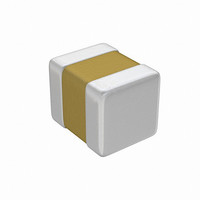
05045C103KA19A AVX Corporation, 05045C103KA19A Datasheet - Page 5

05045C103KA19A
Manufacturer Part Number
05045C103KA19A
Description
CAP CER 10000PF 50V X7R 0504
Manufacturer
AVX Corporation
Datasheet
1.05041A1R0DAT1A.pdf
(48 pages)
Specifications of 05045C103KA19A
Capacitance
10000pF
Voltage - Rated
50V
Tolerance
±10%
Temperature Coefficient
X7R
Mounting Type
Surface Mount, MLCC
Operating Temperature
-55°C ~ 125°C
Features
Low ESL
Applications
General Purpose
Package / Case
0504 (1210 Metric)
Size / Dimension
0.050" L x 0.040" W (1.27mm x 1.02mm)
Thickness
1.02mm Max
Lead Free Status / RoHS Status
Lead free / RoHS Compliant
Ratings
-
Lead Spacing
-
to de-age capacitors and is why re-reading of capacitance
after 12 or 24 hours is allowed in military specifications after
dielectric strength tests have been performed.
Figure 6
Effects of Frequency – Frequency affects capacitance
and impedance characteristics of capacitors. This effect is
much more pronounced in high dielectric constant ceramic
formulation that is low K formulations. AVX’s SpiCap soft-
ware generates impedance, ESR, series inductance, series
resonant frequency and capacitance all as functions of fre-
quency, temperature and DC bias for standard chip sizes
and styles. It is available free from AVX.
General Description
+1.5
-3.0
-4.5
-1.5
-6.0
-7.5
0
1
Characteristic
Typical Curve of Aging Rate
NP0
X7R
Z5U
Y5V
10
X7R Dielectric
100
Max. Aging Rate %/Decade
Hours
1000 10,000 100,000
None
1.5
5
5
Effects of Mechanical Stress – High “K” dielectric
ceramic capacitors exhibit some low level piezoelectric
reactions under mechanical stress. As a general statement,
the piezoelectric output is higher, the higher the dielectric
constant of the ceramic. It is desirable to investigate this
effect before using high “K” dielectrics as coupling capaci-
tors in extremely low level applications.
Reliability – Historically ceramic capacitors have been one
of the most reliable types of capacitors in use today.
The approximate formula for the reliability of a ceramic
capacitor is:
where
Historically for ceramic capacitors exponent X has been
considered as 3. The exponent Y for temperature effects
typically tends to run about 8.
A capacitor is a component which is capable of storing
electrical energy. It consists of two conductive plates (elec-
trodes) separated by insulating material which is called the
dielectric. A typical formula for determining capacitance is:
Capacitance – The standard unit of capacitance is the
farad. A capacitor has a capacitance of 1 farad when 1
coulomb charges it to 1 volt. One farad is a very large unit
and most capacitors have values in the micro (10
(10
Dielectric Constant – In the formula for capacitance given
above the dielectric constant of a vacuum is arbitrarily cho-
sen as the number 1. Dielectric constants of other materials
are then compared to the dielectric constant of a vacuum.
Dielectric Thickness – Capacitance is indirectly propor-
tional to the separation between electrodes. Lower voltage
requirements mean thinner dielectrics and greater capaci-
tance per volume.
Area – Capacitance is directly proportional to the area of
the electrodes. Since the other variables in the equation are
usually set by the performance desired, area is the easiest
parameter to modify to obtain a specific capacitance within
a material group.
V
.224 = conversion constant
L
L
V
-9
o
o
t
) or pico (10
t
C = capacitance (picofarads)
K = dielectric constant (Vacuum = 1)
A = area in square inches
= operating life
= test life
= test voltage
= operating voltage
t = separation between the plates in inches
(thickness of dielectric)
(.0884 for metric system in cm)
-12
L
L
) farad level.
o
t
=
C =
V
V
o
t
X
.224 KA
X,Y = see text
T
T
T
T
o
o
t
t
t
= test temperature and
= operating temperature
Y
in °C
-6
), nano
3


