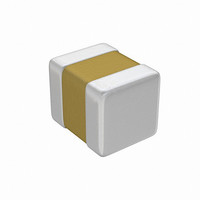
05045C103MA71A AVX Corporation, 05045C103MA71A Datasheet - Page 43

05045C103MA71A
Manufacturer Part Number
05045C103MA71A
Description
CAP CER 10000PF 50V X7R 0504
Manufacturer
AVX Corporation
Datasheet
1.05041A1R0DAT1A.pdf
(48 pages)
Specifications of 05045C103MA71A
Capacitance
10000pF
Voltage - Rated
50V
Tolerance
±20%
Temperature Coefficient
X7R
Mounting Type
Surface Mount, MLCC
Operating Temperature
-55°C ~ 125°C
Features
Low ESL
Applications
General Purpose
Package / Case
0504 (1210 Metric)
Size / Dimension
0.050" L x 0.040" W (1.27mm x 1.02mm)
Thickness
1.02mm Max
Lead Free Status / RoHS Status
Lead free / RoHS Compliant
Ratings
-
Lead Spacing
-
Strength
Flexure
Fracture toughness
Chemical Resistance
Ceramics themselves are very resistant to chemical attack,
providing they are processed in a manner which prevents
the incidence of cracks or chips in the body. In cases where
cracks etc. are present, moisture can penetrate and cause
insulation resistance to reduce.
Termination, whether silver/palladium or nickel barrier solder
coated, can suffer chemical attack from pollutants in the air
or packing materials. In order to preserve their solderability
they should be kept in the packing the manufacturer sup-
plied until required for use. Points to watch are the use of
paper and rubber bands, which contain sulphur com-
pounds.
Handling
Ceramic chips can easily be damaged and contaminated by
poor handling or storage. A chip or crack, contamination by
hands or poor storage, use of metal tweezers (the surface
or bare ceramic chips is very abrasive) can all induce subse-
quent defect as described above. Care must be taken to
achieve the best results.
Surface Mounting Guide
Appendix 1: MLC Capacitors
Exploded View of the
Termination and Capacitor
Body Showing Forces
Exerted by the Termination
Thermal Stress on Terminations.
Ceramic Body
140 MPa
3Gpa
F
Forces Exerted by
the Termination
An Expanding
Rectangular Annulus
F
F
This merely confirms the well known high strength in com-
pression, low strength in tension that ceramics normally
have.
TERMINATION TYPES &
APPLICATIONS
The capacitor termination must be designed so that it has
(a) a good electrical connection to the internal electrode sys-
tem and (b) has good solderability and leaching properties
with normally used fluxes, solders and soldering processes.
Surface mount assembly has permitted the use of a wider
range of soldering processes than was traditionally viable for
pin-through hole manufacture.
This has, in turn, placed greater demands on the capacitor
terminations, especially with regard to wave-soldering and
some of the more prolonged reflow techniques.
Storage
Good solderability is maintained for at least twelve months,
provided the components are stored in their “as received”
packaging at less than 40°C and 70% relative humidity.
Solderability
Terminations to be well tinned after immersion in a 60/40
tin/lead solder bath at 230 ±10°C for 5 ±1 seconds.
F
Each Electrode That Enters
The Capacitor Body Acts
Like A Wedge Forcing The
Capacitor Apart
Thermal stresses on electrodes/ceramic
F
F
F
F
41


