RDER72J152K2K1C11B Murata Electronics North America, RDER72J152K2K1C11B Datasheet - Page 38
RDER72J152K2K1C11B
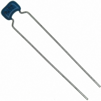
Manufacturer Part Number
RDER72J152K2K1C11B
Description
CAP CER 1500PF 630V X7R RADIAL
Manufacturer
Murata Electronics North America
Series
RDEr
Datasheets
1.RPEF51H104Z2K1A03B.pdf
(2 pages)
2.RDEE41H104M0K1C03B.pdf
(3 pages)
3.RDER72J682K2K1C11B.pdf
(39 pages)
4.RDER72J152K2K1C11B.pdf
(1 pages)
Specifications of RDER72J152K2K1C11B
Capacitance
1500pF
Voltage - Rated
630V
Tolerance
±10%
Temperature Coefficient
X7R
Mounting Type
Through Hole
Operating Temperature
-55°C ~ 125°C
Features
High Voltage
Applications
General Purpose
Package / Case
Radial
Size / Dimension
0.138" L x 0.197" W (3.50mm x 5.00mm)
Thickness
3.15mm Max
Lead Spacing
0.197" (5.00mm)
Lead Style
Flat Bent
Lead Free Status / RoHS Status
Lead free / RoHS Compliant
Ratings
-
Other names
490-4825


4
!Note
• This PDF catalog is downloaded from the website of Murata Manufacturing co., ltd. Therefore, it’s specifications are subject to change or our products in it may be discontinued without advance notice. Please check with our
• This PDF catalog has only typical specifications because there is no space for detailed specifications. Therefore, please approve our product specifications or transact the approval sheet for product specifications before ordering.
sales representatives or product engineers before ordering.
!Note
Capacitance change of capacitor
1. Cleaning (ultrasonic cleaning)
2. Soldering and Mounting
36
In case of X7R/X8L/Y5V char.
Notice
Capacitors have an aging characteristic, whereby
the capacitor continually decreases its capacitance
slightly if the capacitor is left on for a long
time. Moreover, capacitance might change greatly
depending on the surrounding temperature or an
applied voltage.
Notice (Rating)
Notice (Soldering and Mounting)
To perform ultrasonic cleaning, observe the following
conditions.
Rinse bath capacity : Output of 20 watts per liter or less.
Rinsing time : 5 min. maximum.
Do not vibrate the PCB/PWB directly.
Excessive ultrasonic cleaning may lead to fatigue
destruction of the lead wires.
(1) Allowable Conditions for Soldering Temperature and Time
(2) Insertion of the Lead Wire
· When soldering, insert the lead wire into the PCB without
· Insert the lead wire into the PCB with a distance appropriate
mechanically stressing the lead wire.
to the lead space.
• Please read rating and !CAUTION (for storage, operating, rating, soldering, mounting and handling) in this catalog to prevent smoking and/or burning, etc.
• This catalog has only typical specifications because there is no space for detailed specifications. Therefore, please approve our product specifications or transact the approval sheet for product specifications before ordering.
300
280
270
260
240
220
Perform soldering within tolerance range (shaded portion).
q
5
Accumulated Immersion Time (sec.)
w
10
q
w
e
e
1, 2 (F: 2.5mm)
2 (F: 5.0mm), 3, 4, 8
5, 6, 7, U
Dimensions Code
15
20
C49E.pdf
10.3.8
Related parts for RDER72J152K2K1C11B
Image
Part Number
Description
Manufacturer
Datasheet
Request
R

Part Number:
Description:
BUZZER PIEZO 25VP-P SMD
Manufacturer:
Murata Electronics North America

Part Number:
Description:
CAP 4-ARRAY 680PF 100V X7R 1206
Manufacturer:
Murata Electronics North America
Datasheet:
Part Number:
Description:
CAP 4-ARRAY 1000PF 100V X7R 1206
Manufacturer:
Murata Electronics North America
Datasheet:
Part Number:
Description:
CAP 4-ARRAY 1800PF 100V X7R 1206
Manufacturer:
Murata Electronics North America
Datasheet:
Part Number:
Description:
CAP 4-ARRAY 68000PF 16V X7R 1206
Manufacturer:
Murata Electronics North America
Datasheet:

Part Number:
Description:
CAP CER 1000PF 50V 10% X7R 0402
Manufacturer:
Murata Electronics North America
Datasheet:
Part Number:
Description:
CAP CER 10000PF 16V 10% X7R 0402
Manufacturer:
Murata Electronics North America
Datasheet:

Part Number:
Description:
CAP 5.5-25PF 2.5X3.2MM SMD
Manufacturer:
Murata Electronics North America
Datasheet:

Part Number:
Description:
CAP 4.5-20PF 2.5X3.2MM SMD
Manufacturer:
Murata Electronics North America
Datasheet:

Part Number:
Description:
CAP 5.0-20PF 3.2X4.5MM SMD RED
Manufacturer:
Murata Electronics North America
Datasheet:

Part Number:
Description:
CAP 2.0-6.0PF 3.2X4.5MM SMD BLU
Manufacturer:
Murata Electronics North America
Datasheet:

Part Number:
Description:
CAP 1.4-3.0PF 3.2X4.5MM SMD BRN
Manufacturer:
Murata Electronics North America
Datasheet:

Part Number:
Description:
CAP 3.0-10PF 3.2X4.5MM SMD WHT
Manufacturer:
Murata Electronics North America
Datasheet:

Part Number:
Description:
CAP 2.0-6.0PF 4X4.5MM TOPADJ BLU
Manufacturer:
Murata Electronics North America
Datasheet:

Part Number:
Description:
CAP 8.5-40PF 4X4.5MM TOPADJ YEL
Manufacturer:
Murata Electronics North America
Datasheet: