C1812C154J5GACTU Kemet, C1812C154J5GACTU Datasheet
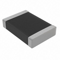
CAP CER .15UF 50V C0G 1812

C1812C154J5GACTU

Manufacturer Part Number
C1812C154J5GACTU
Description
CAP CER .15UF 50V C0G 1812
Manufacturer
Kemet
Series
HiCVr
Type
Flatr

Specifications of C1812C154J5GACTU

Capacitance
0.15µF
Voltage - Rated
50V
Tolerance
±5%
Temperature Coefficient
C0G, NP0
Mounting Type
Surface Mount, MLCC
Operating Temperature
-55°C ~ 125°C
Applications
General Purpose
Package / Case
1812 (4532 Metric)
Size / Dimension
0.177" L x 0.126" W (4.50mm x 3.20mm)
Thickness
1.25mm
Capacitor Application
High CV
Dielectric Characteristic
C0G / NP0
Capacitance Tolerance
± 5%
Voltage Rating
50VDC
Capacitor Case Style
1812
Rohs Compliant
Yes
Package/case
1812
Mounting
Surface Mount
Capacitance Value
0.15 uF
Dielectric
C0G
Voltage
50 Vdc
Product Length
4.5 mm
Product Height
1.25 mm
Product Depth
3.2 mm
Lead Free Status / RoHS Status
Lead free / RoHS Compliant
Features
-
Ratings
-
Lead Spacing
-
Other names
399-5360-2
C1812C154J5GAC
C1812C154J5GAC7800
© KEMET Electronics Corporation • P.O. Box 5928 • Greenville, SC 29606 (864) 963-6300 • www.kemet.com
Surface Mount Ceramic Chip Capacitors –
Ultra-High Capacitance, Large Case Size, C0G Dielectric
Style
C - Ceramic
Size Code
1812, 2220
Capacitance Code, pF
First two digits represent significant figures.
Third digit specifies number of zeros. 100 pF = 101.
(Use “9” for 1.0 through 9.9 pF)
(Use “8” for 0.1 through .99 pF)
Capacitance Tolerance
F = ±1%
G = ±2%
J = ±5%
See Capacitance Value Chart following for thickness dimension.
Specification
C - Standard
Outline Drawing
Dimensions - Millimeters (Inches)
Ordering Information
EIA SIZE
CODE
1812
2220
SIZE CODE
METRIC
4532
5650
K = ±10%
M = ±20%
C 2220
4.5 (.177 ± .30 (.012)
5.6 (.220 ± .40 (.016)
L - LENGTH
C
5.0 (.197) ± .40 (.016) 0.60 (.024) ± .35 (.014)
3.2 (.126 ± .30 (.012)
474
W - WIDTH
J
0.60 (.024) ± .35 (.014)
5
B - BANDWIDTH
G
Product Bulletin
Change Over Temperature Range
A
G = C0G (NP0) (±30 PPM/°C)
Temperature Characteristic
SEPARATION
Designated by Capacitance
minimum
N/A
N/A
C = Standard (Tin-plate
S
C
nickel barrier)
Failure Rate Level
End Metallization
A = Not Applicable
Solder Reflow
Solder Reflow
TECHNIQUE
MOUNTING
F9201 4/08
5 = 50V
1 = 100V
Voltage

Related parts for C1812C154J5GACTU

C1812C154J5GACTU Summary of contents

Page 1

... Capacitance Tolerance F = ± ±10 ± ±20 ±5% © KEMET Electronics Corporation • P.O. Box 5928 • Greenville, SC 29606 (864) 963-6300 • www.kemet.com W - WIDTH B - BANDWIDTH 3.2 (.126 ± .30 (.012) 0.60 (.024) ± .35 (.014) 5.0 (.197) ± .40 (.016) 0.60 (.024) ± .35 (.014) C ...

Page 2

... Electrical Parameters As detailed in the KEMET Surface Mount Catalog F3102 for C0G, with following specific requirements based on room temperature (25°C) parameters: • Operating Range: -55°C to +125°C, with no-bias capacitance shift limited to ± 30 PPM/°C over that range. • Insulation Resistance (IR) measured after 2 minutes at rated voltage @ 25°C: Limit is 1000 megohm microfarads or 100GΩ ...

Page 3

... C2220C104_1GAC 120000 C2220C124_1GAC 150000 C2220C154_1GAC 220000 C2220C224_1GAC 270000 C2220C274_1GAC 330000 C2220C334_1GAC © KEMET Electronics Corporation • P.O. Box 5928 • Greenville, SC 29606 (864) 963-6300 • www.kemet.com Capacitance Thickness Voltage Tolerance mm (inches 1.00 (0.039) ± 0.10 (0.004 1.00 (0.039) ± 0.10 (0.004) ...

Related keywords