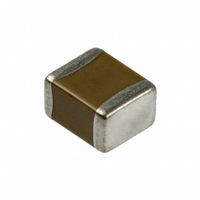
C1210C103JDRACTU Kemet, C1210C103JDRACTU Datasheet - Page 4

C1210C103JDRACTU
Manufacturer Part Number
C1210C103JDRACTU
Description
CAP CERM 10000PF 1000V X7R 1210
Manufacturer
Kemet
Datasheet
1.C1210C103JDRACTU.pdf
(10 pages)
Specifications of C1210C103JDRACTU
Capacitance
10000pF
Voltage - Rated
1000V (1kV)
Tolerance
±5%
Temperature Coefficient
X7R
Mounting Type
Surface Mount, MLCC
Operating Temperature
-55°C ~ 125°C
Features
High Voltage
Applications
General Purpose
Package / Case
1210 (3225 Metric)
Size / Dimension
0.138" L x 0.102" W (3.50mm x 2.60mm)
Thickness
1.40mm
Capacitor Application
High Voltage
Dielectric Characteristic
X7R
Capacitance Tolerance
± 5%
Voltage Rating
1000VDC
Capacitor Case Style
1210
No. Of Pins
2
Rohs Compliant
Yes
Lead Free Status / RoHS Status
Lead free / RoHS Compliant
Ratings
-
Lead Spacing
-
Other names
399-5106-2
C1210C103JDRAC
C1210C103JDRAC7800
C1210C103JDRAC
C1210C103JDRAC7800
84
Capacitance
Cap Tolerance
DF
Voltage Ratings
Operating Temperature Range
25ºC IR @ 500V
125ºC IR @ 500V
-55ºC TCC
+125ºC TCC
Dielectric Strength
Ripple Current
These chips are supplied unmarked. If required, they can be supplied LASER-marked at an extra cost.
Details on the marking format is located on page 97.
KEMET High Voltage Surface Mount MLCC are available packaged in tape and reel configuration, or bulk
bag as outlined on page 83. Please consult factory for waffle packaging options.
The 0805 and 1206 case sizes are suitable for either reflow or wave soldering processes. Sizes 1210 and
larger should be limited to reflow soldering only. All sizes incorporate the standard KEMET barrier layer of
pure nickel with an overplating of pure tin (Sn) for excellent solderability and resistance to solder leaching of
the termination.
©KEMET Electronics Corporation, P.O. Box 5928, Greenville, S.C. 29606, (864) 963-6300
Capacitance Tolerance
C = ±0.25pF*
D = ±0.5pF*
F = ±1%*
G = ±2%*
* Contact KEMET Sales for availability.
Style
C - Ceramic
Chip Size
0805; 1206; 1210; 1808;
1812; 1825; 2220; 2225
Specification
C - Standard
Capacitance Code, pF
First two digits represent significant figures.
Third digit specifies number of zeros. 100 pF = 101.
(Use “9” for 1.0 through 9.9 pF)
(Use “8” for 0.1 through .99 pF)
Property
J = ±5%
K = ±10%
M = ±20%
Recommended Solder Pad Dimensions
CERAMIC CHIP / HIGH VOLTAGE
C
0805
C
Capacitor Ordering Information
C0G: 1 pF to 0.010 µF
X7R: 10 pf to 0.22 µF
25°C, 1.0 ± 0.2 Vrms, 1 kHz (1 MHz for ≤ 1000 pF (C0G only)
C0G: C*, D*, F*, G*, J, K, M
X7R: J, K, M
C0G: 0.1% Max
X7R: 2.5% Max
500 V, 1000 V, 1500 V, 2000 V, 2500 V, 3000 V
From -55C to +125C
100 GΩ or 1000 MΩ-µF, whichever is less
10 GΩ or 100 MΩ-µF, whichever is less
X7R: + 15%
C0G: + 30 ppm / ºC
150% of Rated Voltage for Rated Voltage <1000 V
120% of Rated Voltage for Rated Voltage >=1000V
Consult KEMET Sales Representative
102
Electrical Parameters
Soldering Process
pF
Packaging
Marking
K
C
Specification
R
* Contact KEMET Sales for availability.
A
G – (C0G) (±30ppm/C) (-55°C +125°C)
Change over Temperature Range
R – X7R (±15%) (-55°C +125°C)
C
L = SnPb plated nickel barrier
Temperature Characteristic
Designated by Capacitance
C = 500V
B = 630V
D = 1000V
Failure Rate Level
A = Not Applicable
End Metallization
(SnPb 5% min)
C = Standard
G = 2000V
H = 3000V
F = 1500V
Z = 2500V
Voltage


