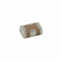
500X14W222MV4T Johanson Dielectrics Inc, 500X14W222MV4T Datasheet - Page 3

500X14W222MV4T
Manufacturer Part Number
500X14W222MV4T
Description
CAP X2Y CER 2200PF 50V X7R 0603
Manufacturer
Johanson Dielectrics Inc
Series
X2Y®r
Specifications of 500X14W222MV4T
Capacitance
2200pF
Voltage - Rated
50V
Tolerance
±20%
Temperature Coefficient
X7R
Mounting Type
Surface Mount, MLCC
Operating Temperature
-55°C ~ 125°C
Features
Low Inductance
Applications
Bypass, Decoupling
Package / Case
0603 (1608 Metric)
Size / Dimension
0.064" L x 0.035" W (1.63mm x 0.89mm)
Thickness
0.66mm Max
Capacitor Application
Safety / Suppression
Dielectric Characteristic
X7R
Capacitance Tolerance
± 20%
Voltage Rating
50VDC
Capacitor Case Style
0603
Rohs Compliant
Yes
Lead Free Status / RoHS Status
Lead free / RoHS Compliant
Ratings
-
Lead Spacing
-
Other names
709-1086-2
X2Y
Filtering
Circuit 1 S21
Signal-to-Ground
M
E
LECTRICAL
CB
EB
ECHANICAL
Temperature Coefficient:
Dielectric Strength:
Dissipation Factor:
Insulation Resistance
(Min. @ 25°C, WVDC)
Test Conditions:
Other:
W
L
T
G1
®
F
0.045 ±
0.003
0.025 ±
0.003
0.020
max
0.008 ±
0.003
0.012 ±
0.003
ILTER
A
B
0402 (X07)
IN
Equivalent Circuits
C
C
HARACTERISTICS
G2
HARACTERISTICS
1.143 ±
0.076
0.635 ±
0.076
0.508
max
0.203 ±
0.076
0.305 ±
0.076
mm
& D
0.064 ±
0.005
0.035 ±
0.005
0.026
max
0.010 ±
0.006
0.018 ±
0.004
ECOUPLING
IN
0603 (X14)
Signal 2
Signal 1
Ground
C ≤ 100 pF; 1Mhz ±50kHz; 1.0±0.2 VRMS
1.626 ±
0.127
0.889 ±
0.127
0.660
max
0.254 ±
0.152
0.457 ±
0.102
C > 100 pF; 1kHz ±50Hz; 1.0±0.2 VRMS
mm
0±30ppm/°C (-55 to +125°C)
G1
0.080 ±
0.008
0.050 ±
0.008
0.040
max
0.012 ±
0.008
0.022 ±
0.005
www.johanson dielectrics.com
B
A
C
0.1% max.
0805 (X15)
IN
Cross-sectional View
NPO
APACITORS
G2
A
2.032 ±
0.203
1.270 ±
0.203
1.016
max
0.305 ±
0.203
0.559 ±
0.127
mm
10.0Ω
1.00Ω
0.10Ω
0.01Ω
See main catalog page 18 for additional dielectric specifications.
G
G
0.124 ±
0.010
0.063 ±
0.010
0.050
max
0.016 ±
0.010
0.040 ±
0.005
C≤ 0.047µF: 1000 ΩF or 100 GΩ, whichever is less
C> 0.047µF: 500 ΩF or 10 GΩ, whichever is less
1206 (X18)
IN
WVDC ≤ 100V: 2.5 X WVDC, 25°C, 50mA max.
WVDC = 500V: 1.4 X WVDC, 25°C, 50mA max.
B
WVDC = 10-16 VDC: 5.0% max.
Decoupling
Circuit 2 S21
Power-to-Ground
Labeled capacitance values below follow the P/N order code or Y cap value (Circuit 1.)
Effective capacitance measured in Circuit 2 is 200% of the labled Circuit 1 Y cap value.
3.150 ±
0.254
1.600 ±
0.254
1.270
max
0.406 ±
0.254
1.016 ±
0.127
WVDC ≥ 50 VDC: 2.5% max.
WVDC = 25 VDC: 3.5% max.
WVDC = 6.3 VDC: 10% max.
mm
±15% (-55 to +125°C)
0.125 ±
0.010
0.098 ±
0.010
0.070
max
0.018 ±
0.010
0.045 ±
0.005
X7R
1210 (X41)
IN
CB
1.0kHz±50Hz @ 1.0±0.2 Vrms
3.175 ±
0.254
2.489 ±
0.254
1.778
max
0.457 ±
0.254
1.143 ±
0.127
mm
Dimensional View
W
0.140 ±
0.010
0.098 ±
0.010
0.070
max
0.018 ±
0.010
0.045 ±
0.005
1410 (X44)
IN
WVDC ≤ 25 VDC: 10% max.
WVDC ≥ 50 VDC: 5% max.
3.556 ±
0.254
2.490 ±
0.254
1.778
max
0.457 ±
0.254
1.143 ±
0.127
±15% (-55 to +85°C)
Ground
Power
mm
EB
L
X5R
0.174 ±
0.010
0.125 ±
0.010
0.090
max
0.022 ±
0.012
0.045 ±
0.005
G1
1812 (X43)
IN
A
B
T
4.420 ±
0.254
3.175 ±
0.254
2.286
max
0.559 ±
0.305
1.143 ±
0.127
G2
mm
10.0Ω
1.00Ω
0.10Ω
0.01Ω
3


