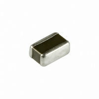
JWK212C6475KD-T Taiyo Yuden, JWK212C6475KD-T Datasheet - Page 32

JWK212C6475KD-T
Manufacturer Part Number
JWK212C6475KD-T
Description
CAP CER 4.7UF 6.3V X6S 0508
Manufacturer
Taiyo Yuden
Series
JWKr
Datasheet
1.LMK105BJ104KV-M.pdf
(51 pages)
Specifications of JWK212C6475KD-T
Capacitance
4.7µF
Voltage - Rated
6.3V
Tolerance
±10%
Temperature Coefficient
X6S
Mounting Type
Surface Mount, MLCC
Operating Temperature
-55°C ~ 105°C
Features
Low ESL
Applications
General Purpose
Package / Case
0805 (2012 Metric) Wide, 0508 (1220 Metric)
Size / Dimension
0.049" L x 0.079" W (1.25mm x 2.00mm)
Thickness
0.85mm
Dielectric Characteristic
X6S
Capacitance Tolerance
± 10%
Voltage Rating
6.3VDC
Capacitor Case Style
0805
No. Of Pins
2
Capacitor Mounting
SMD
Rohs Compliant
Yes
Lead Free Status / RoHS Status
Lead free / RoHS Compliant
Ratings
-
Lead Spacing
-
Other names
587-1237-2
CE JWK212 BJ475KD-T
JWK212BJ475KD-T
CE JWK212 BJ475KD-T
JWK212BJ475KD-T
mlcc06_reli-R1
【Test Methods and Remarks】
【Test Methods and Remarks】
【Test Methods and Remarks】
【Test Methods and Remarks】
【Test Methods and Remarks】
【Test Methods and Remarks】
【Test Methods and Remarks】
【Test Methods and Remarks】
■
MediumーHigh Voltage Multilayer Ceramic Capacitor
5. Insulation Resistance
7. Dissipation Factor
* This catalog contains the typical specification only due to the limitation of space. When you consider the purchase of our products, please check our specification.
1. Operating Temperature Range
Specified Value
2. Storage Temperature Range
Specified Value
3. Rated Voltage
Specified Value
4. Withstanding Voltage ( Between terminals)
Specified Value
Specified Value
6. Capacitance ( Tolerance)
Specified Value
Specified Value
8. Temperature Characteristic of Capacitance
Specified Value
9. Deflection
Specified Value
10. Adhesive Strength of Terminal Electrodes
Specified Value
11. Solderability
Specified Value
Applied voltage:Rated voltage×2.5 ( HMK) , Rated voltage×2 ( QMK) , Rated voltage×1.2 ( SMK)
Duration:1 to 5sec.
Charge/discharge current:50mA max.
Applied voltage:Rated voltage ( HMK, QMK) , 500V ( SMK)
Duration:60±5sec.
Charge/discharge current:50mA max.
Measuring frequency:1kHz±10%
Measuring voltage:1±0.2Vrms
Bias application:None
Measuring frequency:1kHz±10%
Measuring voltage:1±0.2Vrms
Bias application:None
Capacitance value at each step shall be measured in thermal equilibrium, and the temperature characteristic shall be calculated from the following equation.
Warp:1mm
Duration:10sec.
Test board:glass epoxy-resin substrate
Thickness:1.6mm
Capacitance measurement shall be conducted with the board bent.
Applied force:5N
Duration:30±5sec.
For details of each product (characteristics graph, reliability information, precautions for use, and so on), see our Web site (http://www.ty-top.com/) or CD catalogs.
Step
RELIABILITY DATA
Lead-free solder
Eutectic solder
1
2
3
20℃
Maximum operating temperature
Minimum operating temperature
B
Snー3.0Agー0.5Cu
H60A or H63A
Solder type
X5R、 X7R、 X7S
Solder temperature
25℃
230±5℃
245±3℃
±10%、±20%
X7R, X7S:-55~+125℃ X5R:-55~+85℃ B:-25~+85℃
X7R, X7S:-55~+125℃ X5R:-55~+85℃ B:-25~+85℃
100VDC, 250VDC, 630VDC
No breakdown or damage
100MΩ μF or 10GΩ, whichever is smaller.
3.5%max ( HMK)
2.5%max ( QMK, SMK)
B:
X5R: ±15% (-55~+85℃)
X7R: ±15% (-55~+125℃)
X7S: ±22% (-55~+125℃)
Appearance:No abnormality
Capacitance change:Within±10%
No terminal separation or its indication.
At least 95% of terminal electrode is covered by new solder
±10% (-25~+85℃)
4±1 sec.
Duration
(C-C
C
C :Capacitance value in Step 1 or Step 3
C
2
:Capacitance value in Step 2
2
2
)
R-230
×100 ( %)
Multilayer Ceramic Capacitors and Super Low Distortion Multilayer Ceramic
Capacitors are noted separately.
1 1
mlcc06_reli_e-01


