T197A156K015AS Kemet, T197A156K015AS Datasheet - Page 8
T197A156K015AS
Manufacturer Part Number
T197A156K015AS
Description
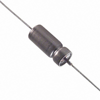
CAP TANT-WET 15UF 15V 10% AXIAL
Manufacturer
Kemet
Series
T197r
Type
Hermetically Sealedr
Datasheet
1.T197A566K008AS.pdf
(28 pages)
Specifications of T197A156K015AS
Capacitance
15µF
Voltage - Rated
15V
Tolerance
±10%
Esr (equivalent Series Resistance)
4.420 Ohm
Operating Temperature
-55°C ~ 200°C
Mounting Type
Through Hole
Package / Case
Axial
Size / Dimension
0.219" Dia x 0.453" L (5.56mm x 11.51mm)
Manufacturer Size Code
A
Features
Wet Tantalum
Lead Free Status / RoHS Status
Contains lead / RoHS non-compliant
Height
-
Lead Spacing
-
Other names
399-3406
T197A156K015AS7340
T197A156K015AS7340


8
•
•
c. Test condition letter - H (80G).
d. Duration and direction of motion - 4 hours in
e. Measurements during vibration - During the
f. Examination after test - Capacitors shall be
Shock Test: Per MIL-STD-202, Method 213.
The following details shall apply:
a. Special mounting means - Capacitors shall
b. Test-condition letter - D (500 G peak). 6 ms.
c. Measurements and electrical loading during
d. Examinations after test - Capacitors shall be
Thermal Shock - MIL-STD-202, Method 107:
Capacitors shall be subjected to thermal shock
in accordance with MIL-STD-202, Method 107,
Test Condition A except step 3 shall be +125°C.
Measurements before and after cycling are
required. Conditioning prior to the first cycle will
be 15 minutes at the following standard inspec-
tion conditions:
a. Number of Cycles: 300 for qualification and
b. Ambient Temperature – 25°C ±5°C
c. Final measurements are made after stabi-
each of two mutually perpendicular directions
(total of 8 hours), one parallel and the other
perpendicular to the axis.
last cycle, an electrical measurement shall be
made to determine intermittent operation or
open- or short-circuiting. Observations shall
also be made to determine intermittent con-
tact or arcing or open- or short-circuiting.
Detecting equipment shall be sufficiently sen-
sitive to detect any interruption with a duration
of 0.5 ms, or greater.
• DC Leakage - shall not exceed 1.25 times
• Capacitance - shall not change more than
• DF - shall not exceed 1.15 times initial limit
visually examined for evidence of mechanical
damage.
be rigidly mounted on a mounting fixture by
the body. When securing leads, care shall be
taken to avoid pinching the heads.
(sawtooth)
shock - During the test, observations shall be
made to determine intermittent contact or arc-
ing or open- or short-circuiting. Detecting
equipment shall be sufficiently sensitive to
detect any interruption with a duration of 0.5
ms. The DC rated voltage shall be applied to
the capacitors during the test.
visually examined for evidence of arcing,
breakdown, and mechanical damage.
Group C
lization at room temperature
initial limit
± 5% from initial limit
© KEMET Electronics Corporation, P.O. Box 5928, Greenville, SC 29606 (864) 963-6300
•
•
•
•
•
Moisture Resistance - MIL-STD-202, Method
106: Capacitors shall be tested in accordance
with MIL-STD-202, Method 106 including the
following details:
a. Mounting - The capacitors shall be mounted
b. Initial Measurements
c. Polarizing and Load Voltage - 6 vdc
d. Final measurements - After the final cycle
Resistance to Solvents - MIL-STD-202,
Method 215:
a. Brushing required after test
b. DCL meets limit shown in respective Part
c. Capacitance meets applicable tolerance
d. DF meets limits shown in respective Part
e. No visible damage to case or marking
Resistance to Soldering Heat - MIL-STD-
202, Method 210, Test Condition, Letter C.
Leads shall be immersed to within 0.05 inch of
the capacitor body. Capacitance, DF, and DCL
should meet original limits shown in respective
Part Number Tables.
Solderability - MIL-STD, Method 208:
a. Number of terminations on each capacitor
b. Depth of insertion in flux and solder to with-
Stability at Low and High Temperature
-55°C to 125°C: Capacitors will be capable of
withstanding extreme temperature testing at a
succession of continuous steps at +25°C, -55°C,
+25°C, +85°C, +125°C, +25°C, in the order stated.
Capacitors shall be brought to thermal stability at
each test temperature. Capacitance, DF, and DCL
are measured at each test temperature except that
DCL is not measured at -55°C, DC bias of 2.0 ±0.5
vdc is recommended for the capacitance and DF
measurements.
When measurements are made at the various
steps, the electrical limits for each temperature
shall not exceed the following limits.
Step 1, +25°C
Step 2, -55°C
by normal mounting means
and within 2 to 6 hours after removal of the
capacitors from the humidity chamber, capa-
citance, dissipation factor, and DC leakage
will be measured per MIL-PRF-39006.
Number Tables
Number Tables
tested: 2
in 0.062” of welded joint
DCL as indicated in original
limit; capacitance within toler-
ance specified; DF as indicat-
ed in original limit shown in
Part Number Tables.
Impedance and capacitance
change as defined in M39006
Slash Sheet.
Related parts for T197A156K015AS
Image
Part Number
Description
Manufacturer
Datasheet
Request
R

Part Number:
Description:
CAP, KEMET #F601BL105K250C
Manufacturer:
Kemet
Datasheet:
Part Number:
Description:
Manufacturer:
Kemet
Datasheet:
Part Number:
Description:
Manufacturer:
Kemet
Datasheet: