C4532X7R2E474K TDK Corporation, C4532X7R2E474K Datasheet - Page 19
C4532X7R2E474K
Manufacturer Part Number
C4532X7R2E474K
Description
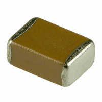
CAP CER .47UF 250V X7R 10% 1812
Manufacturer
TDK Corporation
Series
Cr
Datasheets
1.C1005X7R1E103K.pdf
(1 pages)
2.C1608X7R2A102K.pdf
(26 pages)
3.C3216X7R1E155K.pdf
(17 pages)
Specifications of C4532X7R2E474K
Capacitance
0.47µF
Tolerance
±10%
Package / Case
1812 (4532 Metric)
Voltage - Rated
250V
Temperature Coefficient
X7R
Mounting Type
Surface Mount, MLCC
Operating Temperature
-55°C ~ 125°C
Features
Low ESR
Applications
General Purpose
Size / Dimension
0.177" L x 0.126" W (4.50mm x 3.20mm)
Thickness
2.30mm
Voltage Rating
250 Volts
Operating Temperature Range
- 55 C to + 125 C
Temperature Coefficient / Code
X7R
Product
General Type MLCCs
Dimensions
3.2 mm W x 4.5 mm L x 2.300 mm H
Termination Style
SMD/SMT
Lead Free Status / RoHS Status
Lead free / RoHS Compliant
Ratings
-
Lead Spacing
-
Lead Free Status / Rohs Status
Lead free / RoHS Compliant
Other names
445-2299-2
C4532X7R2E474KT
C4532X7R2E474KT
Available stocks
Company
Part Number
Manufacturer
Quantity
Price
Company:

Part Number:
C4532X7R2E474K
Manufacturer:
AGERE
Quantity:
101
Company:
Part Number:
C4532X7R2E474KT
Manufacturer:
TDK
Quantity:
1 000
Company:
Part Number:
C4532X7R2E474KT0L0U
Manufacturer:
TDK
Quantity:
1 250


• All specifications are subject to change without notice. Please read the precautions before using the product.
No.
8
9
10
11
General
Specifications
Item
Temperature
Characteristics
of Capacitance
(Class 2)
Robustness of
Terminations
Bending
Solderability
Performance
Capacitance Change (%)
No sign of termination coming off,
breakage of ceramic, or other abnormal
signs.
No mechanical damage.
New solder to cover over 75% of
termination.
25% may have pin holes or rough spots
but not concentrated in one spot.
Ceramic surface of A sections shall not
be exposed due to melting or shifting of
termination material.
No Voltage Applied
X7R: ± 15%
X7S: ± 22%
X7T:
+22/-33%
A section
C Series — Mid Voltage Application
Test or Inspection Method
Capacitance shall be measured by the steps shown in
the following table after thermal equilibrium is obtained
for each step.
∆C be calculated ref. STEP 3 reading
Reflow solder the capacitors on P.C. board (shown in
Appendix 1a or Appendix 1b) and apply a pushing
force of 2N (C1005) or 5N (C1608, C2012, C3216,
C3225, C4532, C5750) with 10±1s.
Reflow solder the capacitors on P.C. board (shown in
Appendix 2a or Appendix 2b) and bend 1mm.
Completely soak both terminations in
solder at 235±5°C for 2±0.5s.
Solder : H63A (JIS Z 3282)
Flux : Isopropyl alcohol (JIS K 8839)
Step
US Catalog // C Series — Mid Voltage Application // Version A11
1
2
3
4
Rosin (JIS K 5902) 25% solid solution.
Temperature (ºC)
Reference temp. ± 2
Min. operating temp. ± 2
Reference temp. ± 2
Max. operating temp. ± 2
45
50
Capacitor
20
R230
45
Pushing force
F
P.C. board
Unit: mm
1
Related parts for C4532X7R2E474K
Image
Part Number
Description
Manufacturer
Datasheet
Request
R

Part Number:
Description:
TDK DC to DC Converters, DC to AC Inverters
Manufacturer:
TDK Corporation
Datasheet:
Part Number:
Description:
TDK DC to DC Converters, DC to AC Inverters
Manufacturer:
TDK Corporation
Datasheet: