12101C224KAT2A AVX Corporation, 12101C224KAT2A Datasheet - Page 7
12101C224KAT2A
Manufacturer Part Number
12101C224KAT2A
Description
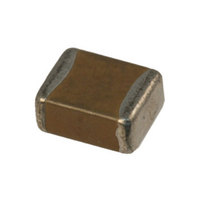
CAP CERM .22UF 10% 100V X7R 1210
Manufacturer
AVX Corporation
Series
1210r
Specifications of 12101C224KAT2A
Capacitance
0.22µF
Tolerance
±10%
Package / Case
1210 (3225 Metric)
Voltage - Rated
100V
Temperature Coefficient
X7R
Mounting Type
Surface Mount, MLCC
Operating Temperature
-55°C ~ 125°C
Applications
General Purpose
Size / Dimension
0.126" L x 0.098" W (3.20mm x 2.50mm)
Thickness
1.52mm Max
Voltage Rating
100 Volts
Operating Temperature Range
- 55 C to + 125 C
Temperature Coefficient / Code
X7R
Product
General Type MLCCs
Dimensions
2.5 mm W x 3.2 mm L x 2.100 mm H
Termination Style
SMD/SMT
Dielectric Characteristic
X7R
Capacitance Tolerance
± 10%
Capacitor Case Style
1210
No. Of Pins
2
Capacitor Mounting
SMD
Rohs Compliant
Yes
Case Size
1210
Material, Element
Ceramic
Termination
SMT
Voltage, Rating
100 VDC
Lead Free Status / RoHS Status
Lead free / RoHS Compliant
Features
-
Ratings
-
Lead Spacing
-
Lead Free Status / Rohs Status
Lead free / RoHS Compliant
Other names
478-1616-6
Available stocks
Company
Part Number
Manufacturer
Quantity
Price

Part Number:
12101C224KAT2A
Manufacturer:
AVX
Quantity:
20 000


Paper Carrier Configuration
8 & 12mm Tape Only
8 & 12mm Paper Tape
Metric Dimensions Will Govern
Bar Code Labeling Standard
AVX bar code labeling is available and follows latest version of EIA-556
CONSTANT DIMENSIONS
VARIABLE DIMENSIONS
NOTES:
1. The cavity defined by A
62
Tape Size
surrounding the component so that:
Tape Size
12mm
8mm
1/2 Pitch
a) the component does not protrude beyond either surface of the carrier tape;
b) the component can be removed from the cavity in a vertical direction without
c) rotation of the component is limited to 20º maximum (see Sketches A & B);
d) lateral movement of the component is restricted to 0.5mm maximum
and
Double
12mm
12mm
mechanical restriction after the top cover tape has been removed;
(see Sketch C).
8mm
8mm
Pitch
0
(0.059
, B
(0.157 ± 0.004)
(0.157 ± 0.004)
(0.079 ± 0.002)
(0.315 ± 0.004)
BOTTOM
1.50
0
, and T shall be configured to provide sufficient clearance
COVER
4.00 ± 0.010
See Note 4
4.00 ± 0.10
2.00 ± 0.05
8.00 ± 0.10
TAPE
D
0
+0.004
-0.0
+0.10
-0.0
P
1
)
(0.069 ± 0.004) (0.157 ± 0.004) (0.079 ± 0.002)
1.75 ± 0.10
T
T
1
T
COVER
1
TAPE
TOP
E
E
(0.246)
(0.404)
(0.246)
(0.404)
10.25
10.25
2
6.25
6.25
CAVITY SIZE
SEE NOTE 1
Min.
0.50mm (0.020)
Maximum
4.00 ± 0.10
Top View, Sketch "C"
Component Lateral
P
0
(0.138 ± 0.002)
(0.217 ± 0.002)
(0.138 ± 0.002)
(0.217 ± 0.002)
D
3.50 ± 0.05
5.50 ± 0.05
3.50 ± 0.05
5.50 ± 0.05
0
CENTER LINES
OF CAVITY
A
0.50mm (0.020)
0
F
2. Tape with or without components shall pass around radius “R” without damage.
3. Bar code labeling (if required) shall be on the side of the reel opposite the sprocket
4. If P
Maximum
B
2.00 ± 0.05
holes. Refer to EIA-556.
0
P
1
2
= 2.0mm, the tape may not properly index in all tape feeders.
P
P
2
0
(0.472 ± 0.012)
(0.472 ± 0.012)
P
12.0 ± 0.30
12.0 ± 0.30
(0.315
(0.315
User Direction of Feed
1
8.00
8.00
10 PITCHES CUMULATIVE
TOLERANCE ON TAPE
±0.20mm (±0.008)
W
+0.012
-0.004
+0.012
-0.004
+0.30
-0.10
+0.30
-0.10
(0.004)
Max.
0.10
T
)
)
E
G
1
F
1
E
2
W
See Note 1
A
0
G. Min.
(0.030)
B
0.75
Min.
0
Base Compositions
for Paper Base
for Non-Paper
(0.043) Max.
(0.063) Max.
25.0 (0.984)
See Note 2
Tape and
1.10mm
1.60mm
R Min.
Min.
T
Related parts for 12101C224KAT2A
Image
Part Number
Description
Manufacturer
Datasheet
Request
R

Part Number:
Description:
Manufacturer:
AVX Corporation
Datasheet:
Part Number:
Description:
Manufacturer:
AVX Corporation
Datasheet:
Part Number:
Description:
Manufacturer:
AVX Corporation
Datasheet:
Part Number:
Description:
Manufacturer:
AVX Corporation
Datasheet:
Part Number:
Description:
Manufacturer:
AVX Corporation
Datasheet: