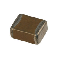
12105C224KAT2A AVX Corporation, 12105C224KAT2A Datasheet

12105C224KAT2A
Manufacturer Part Number
12105C224KAT2A
Description
CAP CERM .22UF 10% 50V X7R 1210
Manufacturer
AVX Corporation
Series
1210r
Specifications of 12105C224KAT2A
Capacitance
0.22µF
Package / Case
1210 (3225 Metric)
Voltage - Rated
50V
Tolerance
±10%
Temperature Coefficient
X7R
Mounting Type
Surface Mount, MLCC
Operating Temperature
-55°C ~ 125°C
Applications
General Purpose
Size / Dimension
0.126" L x 0.098" W (3.20mm x 2.50mm)
Thickness
0.94mm Max
Tolerance (+ Or -)
10%
Voltage
50VDC
Temp Coeff (dielectric)
X7R
Operating Temp Range
-55C to 125C
Mounting Style
Surface Mount
Construction
SMT Chip
Case Style
Ceramic Chip
Failure Rate
Not Required
Wire Form
Not Required
Product Length (mm)
3.2mm
Product Depth (mm)
2.5mm
Product Height (mm)
0.94mm
Product Diameter (mm)
Not Requiredmm
Dielectric Characteristic
X7R
Capacitance Tolerance
± 10%
Voltage Rating
50VDC
Capacitor Case Style
1210
No. Of Pins
2
Capacitor Mounting
SMD
Rohs Compliant
Yes
Case Size
1210
Dielectric Strength
No breakdown or visual defects
Insulation Resistance
100000 Megohms or 1000 Megohms
Length
0.126 in. +⁄- 0.008 in.
Material, Element
Ceramic
Temperature, Operating, Maximum
125 °C
Temperature, Operating, Minimum
-55 °C
Termination
SMT
Voltage, Rating
50 VDC
Width
0.098 in. +⁄- 0.008 in.
Operating Temperature Range
- 55 C to + 125 C
Temperature Coefficient / Code
X7R
Product
General Type MLCCs
Dimensions
2.5 mm W x 3.2 mm L x 2.100 mm H
Termination Style
SMD/SMT
Lead Free Status / RoHS Status
Lead free / RoHS Compliant
Features
-
Ratings
-
Lead Spacing
-
Lead Free Status / Rohs Status
RoHS Compliant part
Other names
478-1619-2
How to Order
Part Number Explanation
Commercial Surface Mount Chips
EXAMPLE: 08055A101JAT2A
High Voltage Surface Mount Chips
EXAMPLE: 1808AA271KA11A
2
(L" x W")
0805
Size
0201
0402
0603
0805
1206
1210
1812
1825
2220
2225
1808
Style
1206
1210
1808
1812
1825
2220
2225
3640
AVX
D = 35V
Voltage
Z = 10V
Y = 16V
F = 63V
* = 75V
E = 150V
V = 250V
4 = 4V
6 = 6.3V
3 = 25V
5 = 50V
1 = 100V
2 = 200V
7 = 500V
Contact Factory for
Special Voltages
5
W = 2500V
G = 2000V
C = 600V
A = 1000V
S = 1500V
H = 3000V
K = 5000V
J = 4000V
Voltage
A
W = X6S
G = Y5V
C = X7R
D = X5R
U = U Series
A = NP0(C0G)
Z = X7S
9 = 300V
X = 350V
8 = 400V
Dielectric
A
Temperature
Coefficient
C = X7R
A = C0G
A
Decimal point, e.g.,
100 = 10 pF
101 = 100 pF
102 = 1000 pF
223 = 22000 pF
224 = 220000 pF
105 = 1µF
106 = 10µF
107 = 100µF
For values below
Capacitance
10 pF, use “R”
9.1 pF = 9R1.
No. of Zeros
2 Sig. Fig +
220,000 pF = 224
Examples:
in place of
22,000 pF = 223
1,000 pF = 102
101
(2 significant digits
+ no. of zeros)
Examples:
100 pF = 101
Capacitance
10 pF = 100
1 µF = 105
Code
271
M = ±20%
C = ±.25 pF
D = ±.50 pF
G = ±2% (≥ 10 pF)
B = ±.10 pF
K = ±10%
P = +100%, -0%
F = ±1% (≥ 10 pF)
Z = +80%, -20%
J = ±5%
C0G: J = ±5%
Tolerance
X7R: K = ±10%
Capacitance
Tolerance
J*
M = ±20%
M = ±20%
K = ±10%
K
Z = +80%,
-20%
4 = Automotive
Applicable
Failure
A = N/A
Rate
Failure
A=Not
Rate
A
A
1 = Pd/Ag Term
Z = Soft
* B, C & D tolerance for ≤10 pF values.
1= Pd/Ag
T = Plated Ni
Standard Tape and Reel material (Paper/Embossed)
depends upon chip size and thickness.
See individual part tables for tape material type for
each capacitance value.
Terminations
T = Plated Ni
7 = Gold Plated
J = Tin/Lead
Termination
Factory For
Termination
Contact
and Sn
and Sn
1
T
Factory For
2 = 7" Reel
4 = 13" Reel
7 = Bulk Cass.
9 = Bulk
Packaging
Packaging/Marking
Multiples
Contact
1A = 7" Reel
3A = 13" Reel
9A = Bulk/Unmarked
Available
2
Unmarked
Unmarked
1A
Special
A = Std.
Code
A
Related parts for 12105C224KAT2A
12105C224KAT2A Summary of contents
Page 1
How to Order Part Number Explanation Commercial Surface Mount Chips EXAMPLE: 08055A101JAT2A 0805 5 A Size Voltage Dielectric Capacitance (L" x W" NP0(C0G) 2 Sig. Fig + 0201 X7R No. ...
Page 2
... Style Case Array Number Voltage Size of Caps 0405 Z = 10V 2 = 0508 Y = 16V 3 = 0612 3 = 25V 5 = 50V 1 = 100V Low Inductance Capacitors (LICC) EXAMPLE: 0612ZD105MAT2A 0612 Z D Size Voltage Dielectric 0306 X7R 0508 Z = 10V D = X5R 0612 Y = 16V 3 = 25V 5 = 50V Interdigitated Capacitors (IDC) ...
Page 3
... C from -55°C to +125°C. Capacitance drift or hysteresis for C0G (NP0) ceramics is negligible at less than ±0.05% versus up to ±2% for films. Typical capacitance change with life is less than ±0.1% for C0G (NP0), one-fifth that shown by most other dielectrics ...


