C1220X7R1H223K TDK Corporation, C1220X7R1H223K Datasheet - Page 11
C1220X7R1H223K
Manufacturer Part Number
C1220X7R1H223K
Description
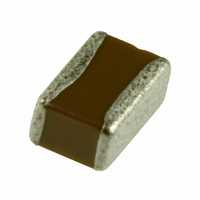
CAP CER .022UF 50V 10% X7R 0508
Manufacturer
TDK Corporation
Series
Cr
Datasheet
1.C0816X7R1C103K.pdf
(15 pages)
Specifications of C1220X7R1H223K
Capacitance
0.022µF
Voltage - Rated
50V
Tolerance
±10%
Temperature Coefficient
X7R
Mounting Type
Surface Mount, MLCC
Operating Temperature
-55°C ~ 125°C
Features
Low ESL
Applications
General Purpose
Package / Case
0805 (2012 Metric) Wide, 0508 (1220 Metric)
Size / Dimension
0.049" L x 0.079" W (1.25mm x 2.00mm)
Thickness
0.85mm
Lead Free Status / RoHS Status
Lead free / RoHS Compliant
Ratings
-
Lead Spacing
-
Other names
445-1804-2
C1220X7R1H223KT
C1220X7R1H223KT


• All specifications are subject to change without notice. Please read the precautions before using the product.
No.
14
15
*As for the initial measurement of capacitors on number 6, 10, 11, 12 and 13, leave capacitor at 150 -10, 0°C for 1h and
measure the value after leaving capacitor for 24 ± 2h in ambient condition.
General
Specifications
Item
Moisture Resistance
External
appearance
Capacitance
D.F. (Class 2)
Insulation
Resistance
Life
External
appearance
Capacitance
D.F. (Class 2)
Insulation
Resistance
Performance
No mechanical damage.
Characteristics
X7R: 200% of initial spec. max.
X7S: 200% of initial spec. max.
X5R: 200% of initial spec. max.
X6S: 200% of initial spec. max.
500MΩ or 25MΩ•μF min. (whichever
smaller). As for the capacitor of rated
voltage 16, 10, 6.3 and 4V DC,
5MΩ•μF min.
No mechanical damage.
Characteristics
X7R: 200% of initial spec. max.
X7S: 200% of initial spec. max.
X5R: 200% of initial spec. max.
X6S: 200% of initial spec. max.
1,000MΩ or 50MΩ•μF min.
whichever smaller. As for the capacitor
of rated voltage 16, 10, 6.3 and 4V DC,
10MΩ•μF min.
Characteristics
Class 2
Characteristics
Class 2
X7R
X7S
X5R
X6S
X7R
X7S
X5R
X6S
Change from the
value before test
± 12.5 %
Change from the
value before test
± 15 %
C Series — Low ESL Flipped Type
Test or Inspection Method
Solder the capacitors on P.C. board (shown in
Appendix 1) before testing.
Apply the rated voltage at temperature 40 ± 2ºC and
90 to 95%RH for 500 +24, 0h.
Charge/discharge current shall not exceed 50mA.
Leave the capacitor in ambient conditions for 48 ± 4h
before measurement.
Voltage conditioning:
Voltage treats the capacitor under testing temperature
and voltage for 1hour.
Leave the capacitor in ambient conditions for 24 ± 2h
before measurement.
Use this measurement for initial value.
Reflow Solder the capacitor on P.C. board (shown in
Appendix 1) before testing.
Apply rated voltage at maximum operating temperature
± 2ºC for 1,000 +48, 0h.
Charge/discharge current shall not exceed 50mA.
Leave the capacitor in ambient conditions for 24 ± 2h
before measurement.
Voltage conditioning:
Voltage treats the capacitor under testing temperature
and voltage for 1hour.
Leave the capacitor in ambient conditions for 48 ± 4h
before measurement.
Use this measurement for initial value.
US Catalog // C Series — Flipped Type // Version A11
Related parts for C1220X7R1H223K
Image
Part Number
Description
Manufacturer
Datasheet
Request
R

Part Number:
Description:
TDK DC to DC Converters, DC to AC Inverters
Manufacturer:
TDK Corporation
Datasheet:
Part Number:
Description:
TDK DC to DC Converters, DC to AC Inverters
Manufacturer:
TDK Corporation
Datasheet: