2222 118 35221 Vishay, 2222 118 35221 Datasheet - Page 7
2222 118 35221
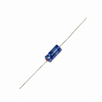
Manufacturer Part Number
2222 118 35221
Description
CAP 16V 220UF ELECT AXIAL
Manufacturer
Vishay
Series
AHT 118r
Specifications of 2222 118 35221
Capacitance
220µF
Voltage Rating
16V
Tolerance
±20%
Lifetime @ Temp.
4000 Hrs @ 125°C
Operating Temperature
-40°C ~ 125°C
Features
General Purpose
Ripple Current
145mA
Esr (equivalent Series Resistance)
1.810 Ohm
Impedance
1.5 Ohm
Mounting Type
Through Hole
Package / Case
Axial, Can
Size / Dimension
0.315" Dia x 0.709" L (8.00mm x 18.00mm)
Capacitance Tolerance
± 20%
Esr
1.8ohm
Life Time @ Temperature
2000 Hours @ 125°C
Height
18mm
Diameter
8mm
Capacitor Mounting
Through Hole
Rohs Compliant
Yes
Lead Free Status / RoHS Status
Lead free / RoHS Compliant
Height
-
Lead Spacing
-
Surface Mount Land Size
-
Other names
4116PHCT


www.vishay.com
230
118 AHT
Vishay BCcomponents
ESR
ESR
CAPACITANCE
EQUIVALENT SERIES RESISTANCE (ESR)
C
ESR
C
ESR
Case Ø D x L = 6.5 mm x 18 mm to 10 mm x 25 mm
ESR
0
Case Ø D x L = 6.5 mm x 18 mm to 10 mm x 25 mm
C 0 = capacitance at 20 °C, 100 Hz
0
1.2
1.0
0.8
0.6
0.4
0.2
2.0
1.6
1.2
0.8
0.4
10
10
10
0
0
0
1
Case Ø D x L = 6.5 mm x 18 mm to 10 mm x 25 mm
ESR
-1
0
2
- 100
= typical at 20 °C, 100 Hz
10
10
0
Curve 1: 63 V to 200 V (< 15 µF)
Curve 2: 63 V; 100 V (< 15 µF)
Curve 3: 40 V
Curve 4: 25 V
Curve 5: 16 V
Curve 6: 10 V
Curve 7: 6.3 V
= typical at 20 °C, 100 Hz
Fig.7 Typical multiplier of capacitance as a function
Fig.11 Typical multiplier of ESR as a function
Fig.9 Typical multiplier of ESR as a function
1
2
3
4
- 50
10 2
10
2
of ambient temperature
of frequency
of frequency
0
10 3
Curve 1: 63 V to 100 V (< 15 µF)
Curve 2: 40 V
Curve 3: 25 V
Curve 4: 6.3 V; 10 V; 16 V
10
3
For technical questions, contact:
50
Curve 1: 100 V; 200 V
Curve 2: 25 V; 40 V; 63 V
Curve 3: 6.3 V; 10 V; 16 V
10 4
10
7
6
4
5
100
4
3
3
2
1
4
3
T
Axial High Temperature
2
f (Hz)
f (Hz)
1
amb
Aluminum Capacitors
(°C)
1
2
3
150
10 5
10
5
aluminumcaps1@vishay.com
ESR
Case Ø D x L = 6.5 mm x 18 mm to 10 mm x 25 mm
ESR
ESR
ESR
C
ESR
C
0
Case Ø D x L = 10 mm x 30 mm to 21 mm x 38 mm
C
10
10
10
1.1
1.0
0.9
0.8
0.7
0.6
0.5
1.6
1.2
0.8
0.4
1
0
0
0
0
- 100
0
-1
Case Ø D x L = 10 mm x 30 mm to 21 mm x 38 mm
ESR
2
= capacitance at 20 °C, 100 Hz
= typical at 20 °C, 100 Hz
10
10
0
= typical at 20 °C, 100 Hz
Fig.8 Typical multiplier of capacitance as a function
Curve 1: 200 V
Curve 2: 100 V
Curve 3: 63 V
Curve 4: 40 V
Curve 5: 25 V
Curve 6: 16 V
Curve 7: 10 V
Curve 8: 6.3 V
8
1
Fig.10 Typical multiplier of ESR as a function
Fig.12 Typical multiplier of ESR as a function
3
1
2
- 50
2
3
4
5
1
10
2
of ambient temperature
10
2
of frequency
0
of frequency
10
3
Curve 1: 6.3 V to 10 V; 16 V
Curve 2: 25 V; 40 V; 63 V
Curve 3: 100 V; 200 V
50
Document Number: 28334
10
Curve 1: 200 V
Curve 2: 100 V
Curve 3: 40 V; 63 V
Curve 4: 16 V; 25 V
Curve 5: 6.3V; 10 V
3
Revision: 06-Sep-10
10
100
4
f (Hz)
T
amb
5
4
3
2
1
f (Hz)
(°C)
1
2
3
4
5
6
7
8
150
3
2
1
10
10
4
5
Related parts for 2222 118 35221
Image
Part Number
Description
Manufacturer
Datasheet
Request
R

Part Number:
Description:
CAP 40V 220UF ELECT AXIAL
Manufacturer:
Vishay
Datasheet:

Part Number:
Description:
CAP 200V 2.2UF ELECT AXIAL
Manufacturer:
Vishay
Datasheet:
Part Number:
Description:
CAPACITOR ALUM ELECT 2200UF, 10V, AXIAL
Manufacturer:
Vishay
Datasheet:

Part Number:
Description:
CAPACITOR ALUM ELECT 4700UF, 10V, AXIAL
Manufacturer:
Vishay
Datasheet:
Part Number:
Description:
CAPACITOR ALUM ELECT 1000UF, 16V, AXIAL
Manufacturer:
Vishay
Datasheet:
Part Number:
Description:
CAPACITOR ALUM ELECT 1500UF, 16V, AXIAL
Manufacturer:
Vishay
Datasheet:
Part Number:
Description:
CAPACITOR ALUM ELECT 2200UF, 16V, AXIAL
Manufacturer:
Vishay
Datasheet:
Part Number:
Description:
CAPACITOR ALUM ELECT 4700UF, 16V, AXIAL
Manufacturer:
Vishay
Datasheet:
Part Number:
Description:
CAPACITOR ALUM ELECT 1000UF, 25V, AXIAL
Manufacturer:
Vishay
Datasheet:
Part Number:
Description:
CAPACITOR ALUM ELECT 2200UF, 25V, AXIAL
Manufacturer:
Vishay
Datasheet:

Part Number:
Description:
357-036-542-201 CARDEDGE 36POS DL .156 BLK LOPRO
Manufacturer:
Vishay
Datasheet:
Part Number:
Description:
357-036-542-201 CARDEDGE 36POS DL .156 BLK LOPRO
Manufacturer:
Vishay
Datasheet:
Part Number:
Description:
357-036-542-201 CARDEDGE 36POS DL .156 BLK LOPRO
Manufacturer:
Vishay
Datasheet:
Part Number:
Description:
357-036-542-201 CARDEDGE 36POS DL .156 BLK LOPRO
Manufacturer:
Vishay
Datasheet:
Part Number:
Description:
357-036-542-201 CARDEDGE 36POS DL .156 BLK LOPRO
Manufacturer:
Vishay
Datasheet: