SOLID TANTALUM ELECTROLYTIC CAPACITORS
Conformal coated Chip, For Mobile Audio
Applications
Feature
Compliant to the RoHS directive (2002/95/EC).
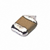
Solder electrode
Type numbering system (Example : 4V 220µF)
Drawing
Mobile Audio Player
Digital video camcorder
Rich sound in the bass register and clear sound,Materials
Low ESR, Low ESL
Line up miniature size and high capacitance, necessary to
are strictly selected to achieve high level sound.
F95 series has no lead-frame, and no vibration factor.
mobile design.
F
1
9
2
MUSE
Resin
5
3
0
4
Single-side electrodes
(Both electrodes at bottom side only)
G
A
5
2
6
L
B
2
7
C
7
8
(D)
Solder
M
F95
9
H
10
A
electrode
Digital still camera
Mobile phone
11
A
12
(Refer to page 321 for details)
W
M
13
14
1
Capacitance tolerance
Q
15
MUSE series code
Rated capacitance
16
2
Rated voltage
Taping code
Single face
Case code
electrode
Series
D dimension only for reference
Case code
Category
Temperature Range
Dissipation Factor
Leakage Current
Capacitance Change
by Temperature
Damp Heat
(Steady State)
Temperature Cycles
Resistance to
Soldering Heat
Surge
Endurance
Shear Test
Terminal Strength
Capacitance Tolerance
As for the surge and derated voltage at 125 ˚C , refer to page 320 for details.
ESR(100kHz)
Specifications
Dimensions
(at 120Hz)
P
S
A
T
B
Item
2.2 ± 0.3 1.25 ± 0.3 1.0 ± 0.2
3.2 ± 0.3
3.2 ± 0.3
3.5 ± 0.2
3.5 ± 0.2
L
+15% Max. (at +125 ˚C )
+10% Max. (at + 85 ˚C )
--10% Max. (at --55 ˚C )
--55 to +125 ˚C (Rated temperature : +85 ˚C )
± 20% (at 120Hz)
Reflow at 260 ˚C for 10 seconds
Refer to next page
Refer to next page
Refer to next page
Provided that
At --55˚C / +125˚C, 30 minutes each, For 5 cycles,
Capacitance Change
Dissipation Factor
Leakage Current
After application of surge voltage in series with a 33 resistor at the rate of 30
seconds ON, 30 seconds OFF, for 1000 successive test cycles at 85 ˚C ,
capacitors meet the characteristics requirements listed below.
After 2000 hours' application of rated voltage at 85 ˚C , or derated voltage at
125 ˚C , capacitors meet the characteristic requirements listed below.
After applying the pressure load of 5N
center of capacitor side body which has
no electrode and has been soldered
beforehand on an aluminum substrate,
there shall be found neither exfoliation
nor its sign at the terminal electrode.
Keeping a capacitor surface-mounted on a substrate upside
down and supporting the substrate at both of the opposite
bottom points 45mm apart from the center of the capacitor,
the pressure strength is applied with
a specified jig at the center of the
substrate so that the substrate may
bend by 1mm as illustrated. Then,
there shall be found no remarkable
abnormality on the capacitor terminals.
At 40 ˚C , 90 to 95% R.H., For 500 hours (No voltage applied)
for 10 ± 1 seconds horizontally to the
•
•
After 1 minute's application of rated voltage, leakage current at 85 ˚C,
After 1 minute's application of rated voltage, leakage current at 125 ˚C,
Capacitance Change
Dissipation Factor
Leakage Current
10 times or less than 20˚C specified value.
12.5 times or less than 20˚C specified value.
Leakage Current
Capacitance Change
Dissipation Factor
Capacitance Change
Dissipation Factor
Leakage Current
Capacitance Change
Dissipation Factor
Leakage Current
1.6 ± 0.3
1.7 ± 0.3
2.7 ± 0.2
2.8 ± 0.2
W
1.0 ± 0.2
1.4 ± 0.2
1.0 ± 0.2
1.8 ± 0.2
• • • • • • • • • • •• • • •
• • • • • • • • • • • • •
H
• • • • • • • • • • • •
• • • • • • • • • • ••
• • • • • • • • • • • •
• • • • • • • • • • ••
• • • • • • • • • •
• • • • • • • • • •
• • • • • • • • • •
• • • • • • • • • •
Per formance Characteristics
• • • • • • • • •
• • • • • •
• • • • • •
• • • • • •
• • • • • •
0.6 ± 0.3
0.8 ± 0.3
0.8 ± 0.3
0.8 ± 0.2
0.8 ± 0.3
Refer to next page ( 1)
Initial specified value or less
Initial specified value or less
Refer to next page ( 1)
Refer to next page ( 1)
Initial specified value or less
Initial specified value or less
Refer to next page ( 1)
Initial specified value or less
Initial specified value or less
Initial specified value or less
Initial specified value or less
Refer to next page ( 1)
Initial specified value or less
Initial specified value or less
A
0.8 ± 0.3
1.2 ± 0.3
1.2 ± 0.3
1.2 ± 0.2
1.2 ± 0.3
B
0.8 ± 0.3
0.8 ± 0.3
0.8 ± 0.3
1.1 ± 0.2
1.1 ± 0.3
R230
C
5N (0.51kg
For 10
45
CAT.8100Z
45
(0.2)
(0.2)
(0.2)
(0.2)
(0.2)
( D )
1 seconds
20
(mm)
•
f)