MAL202118102E3 Vishay, MAL202118102E3 Datasheet - Page 7
MAL202118102E3
Manufacturer Part Number
MAL202118102E3
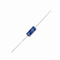
Description
CAP 63V 1000UF ELECT AXIAL
Manufacturer
Vishay
Series
ASM 021r
Datasheet
1.MAL202138477E3.pdf
(8 pages)
Specifications of MAL202118102E3
Capacitance
1000µF
Voltage Rating
63V
Tolerance
±20%
Lifetime @ Temp.
8000 Hrs @ 85°C
Operating Temperature
-40°C ~ 85°C
Features
General Purpose
Ripple Current
1.17A
Esr (equivalent Series Resistance)
135.0 mOhm
Impedance
75 mOhm
Mounting Type
Through Hole
Package / Case
Axial, Can
Size / Dimension
0.709" Dia x 1.181" L (18.00mm x 30.00mm)
Esr
0.135 Ohms
Operating Temperature Range
- 40 C to + 85 C
Termination Style
Axial
Dimensions
18 mm Dia. x 30 mm L
Product
General Purpose Electrolytic Capacitors
Mounting
Through Hole
Capacitance Value
1000 uF
Voltage
63 Vdc
Product Length
30 mm
Lead Free Status / RoHS Status
Lead free / RoHS Compliant
Height
-
Lead Spacing
-
Surface Mount Land Size
-
Lead Free Status / Rohs Status
Lead free / RoHS Compliant
Other names
2222 021 18102
222202118102
4081PHBK
MAL202118102
222202118102
4081PHBK
MAL202118102


021 ASM
Vishay BCcomponents
Table 4
Table 5
www.vishay.com
178
MULTIPLIER OF RIPPLE CURRENT (I
TEST PROCEDURES AND REQUIREMENTS
Endurance
Useful life
Shelf life
(storage at
high temperature)
NAME OF TEST
10 000
FREQUENCY
1000
3000
100
300
(Hz)
50
TEST
IEC 60384-4/
EN130300
subclause 4.13
CECC 30301
subclause 1.8.1
IEC 60384-4/
EN130300
subclause 4.17
REFERENCE
For technical questions, contact:
U
R
= 6.3 V to 16 V
0.95
1.00
1.07
1.12
1.15
1.20
Axial Standard Miniature
Aluminum Capacitors
R
T
case Ø D x L = 4.5 mm x 10 mm to
U
U
case Ø D x L = 10 mm x 30 m to
U
T
case Ø D x L = 10 mm x 30 mm to
T
case Ø D x L = 4.5 mm x 10 mm to
case Ø D x L = 10 mm x 30 mm to
T
500 h
after test: U
24 h to 48 h before measurement
) AS A FUNCTION OF FREQUENCY
amb
amb
amb
amb
R
R
R
= 6.3 V to 25 V: 1000 h;
= 40 V to 100 V: 2000 h;
= 6.3 to 100 V: 5000 h
= 85 °C; U
= 105 °C; U
= 85 °C; U
= 85 C; no voltage applied;
(quick reference)
R
aluminumcaps1@vishay.com
PROCEDURE
to be applied for 30 min,
10 mm x 25 mm:
21 mm x 38 mm:
21 mm x 38 mm: 2000 h
10 mm x 25 mm: 2500 h;
21 mm x 38 mm: 8000 h
R
R
R
applied;
and I
applied;
U
I
R
R
R
= 25 V to 40 V
MULTIPLIER
applied;
0.90
1.00
1.12
1.20
1.25
1.30
U
U
tan 1.3 x spec. limit
Z 2 x spec. limit
I
C/C: ± 20 %
tan 1.6 x spec. limit
Z 2 x spec. limit
I
U
U
tan 3 x spec. limit
Z 3 x spec. limit
I
no short or open circuit
total failure percentage: 1 %
C/C, tan , Z:
for requirements
see ‘Endurance test’ above
I
L5
L5
L5
L5
R
R
R
R
spec. limit
spec. limit
spec. limit
2 x spec. limit
6.3 V; C/C: + 15 %/- 30 %
6.3 V; C/C: ± 15 %
6.3 V; C/C: + 45 %/- 50 %
6.3 V; C/C: ± 45 %
REQUIREMENTS
U
R
Document Number: 28325
= 63 V to 100 V
0.85
1.00
1.20
1.30
1.35
1.40
Revision: 14-Feb-11
Related parts for MAL202118102E3
Image
Part Number
Description
Manufacturer
Datasheet
Request
R

Part Number:
Description:
357-036-542-201 CARDEDGE 36POS DL .156 BLK LOPRO
Manufacturer:
Vishay
Datasheet:
Part Number:
Description:
357-036-542-201 CARDEDGE 36POS DL .156 BLK LOPRO
Manufacturer:
Vishay
Datasheet:
Part Number:
Description:
357-036-542-201 CARDEDGE 36POS DL .156 BLK LOPRO
Manufacturer:
Vishay
Datasheet:
Part Number:
Description:
357-036-542-201 CARDEDGE 36POS DL .156 BLK LOPRO
Manufacturer:
Vishay
Datasheet:
Part Number:
Description:
357-036-542-201 CARDEDGE 36POS DL .156 BLK LOPRO
Manufacturer:
Vishay
Datasheet:
Part Number:
Description:
357-036-542-201 CARDEDGE 36POS DL .156 BLK LOPRO
Manufacturer:
Vishay
Datasheet:
Part Number:
Description:
357-036-542-201 CARDEDGE 36POS DL .156 BLK LOPRO
Manufacturer:
Vishay
Datasheet:
Part Number:
Description:
357-036-542-201 CARDEDGE 36POS DL .156 BLK LOPRO
Manufacturer:
Vishay
Datasheet:
Part Number:
Description:
357-036-542-201 CARDEDGE 36POS DL .156 BLK LOPRO
Manufacturer:
Vishay
Datasheet:
Part Number:
Description:
357-036-542-201 CARDEDGE 36POS DL .156 BLK LOPRO
Manufacturer:
Vishay
Datasheet:
Part Number:
Description:
357-036-542-201 CARDEDGE 36POS DL .156 BLK LOPRO
Manufacturer:
Vishay
Datasheet:
Part Number:
Description:
357-036-542-201 CARDEDGE 36POS DL .156 BLK LOPRO
Manufacturer:
Vishay
Datasheet:
Part Number:
Description:
357-036-542-201 CARDEDGE 36POS DL .156 BLK LOPRO
Manufacturer:
Vishay
Datasheet:
Part Number:
Description:
357-036-542-201 CARDEDGE 36POS DL .156 BLK LOPRO
Manufacturer:
Vishay
Datasheet:
Part Number:
Description:
357-036-542-201 CARDEDGE 36POS DL .156 BLK LOPRO
Manufacturer:
Vishay
Datasheet: