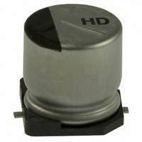
EEE-HD1HR47R Panasonic - ECG, EEE-HD1HR47R Datasheet - Page 24

EEE-HD1HR47R
Manufacturer Part Number
EEE-HD1HR47R
Description
CAP .47UF 50V ELECT HD SMD
Manufacturer
Panasonic - ECG
Series
HDr
Datasheet
1.EEE-HD1H1R0R.pdf
(26 pages)
Specifications of EEE-HD1HR47R
Capacitance
0.47µF
Voltage Rating
50V
Tolerance
±20%
Lifetime @ Temp.
5000 Hrs @ 105°C
Operating Temperature
-40°C ~ 105°C
Features
General Purpose
Ripple Current
5mA
Impedance
12 Ohm
Mounting Type
Surface Mount
Package / Case
Radial, Can - SMD
Size / Dimension
0.157" Dia (4.00mm)
Height
0.228" (5.80mm)
Surface Mount Land Size
0.169" L x 0.169" W (4.30mm x 4.30mm)
Lead Free Status / RoHS Status
Lead free / RoHS Compliant
Lead Spacing
-
Esr (equivalent Series Resistance)
-
Other names
EEEHD1HR47R
PCE4971TR
PCE4971TR
1.3 Common Application Conditions to Avoid
1.4 Using Two or More Capacitors in Series or Parallel
1.5 Capacitor Mounting Considerations
1.6 Electrical Isolation of the Capacitor
1.7 Capacitor Sleeve
(3) Clearance for Case Mounted Pressure Relief (≧φ10 mm)
(4) Wiring Near the Pressure Relief (≧φ10 mm)
(5) Circuit Board Patterns Under the Capacitor
of electrolyte. Under extreme conditions, explosion and fire ignition could result.
The leaked electrolyte is combustible and electrically conductive.
(1) Reverse Voltage
(2) Charge / Discharge Applications
(4) Over voltage
(5) Ripple Current
(1) Capacitors Connected in Parallel
(2) Capacitors Connected in Series
(1) Double-Sided Circuit Boards
(2) Land/ Pad Pattern
Completely isolate the capacitor as follows.
・ Between the cathode and the case and between the anode terminal and other circuit paths.
The following misapplication load conditions will cause rapid deterioration of a capacitor’s electrical parameters.
In addition, rapid heating and gas generation within the capacitor can occur, causing the pressure relief vent to operate and resultant leakage
(3) ON-OFF circuit
The laminate coating is intended for marking and identification purposes and is not meant to electrically insulate the capacitor.
※
Capacitors with case mounted pressure relief require sufficient clearance to allow for proper pressure relief operation.
The minimum clearance are dependent on capacitor diameters as follows.
(Dia 10mm ~ Dia 16mm : 2mm minimum , Dia 18mm : 3mm minimum)
Avoid locating high voltage or high current wiring or circuit board paths above the pressure relief . Flammable, high temperature gas that
exceeds 100 ゚ C may be released which could dissolve the wire insulation and ignite.
Do not use capacitors in circuit where ON-OFF switching is repeated more than 10000 times/per day.
In case of applying to the theses ON-OFF circuit, consult with us about circuit condition and so on.
Avoid circuit board runs under the capacitor, as an electrical short can occur due to an electrolyte leakage.
capacitors. DC bipolar capacitors are not suitable for use in AC circuits.
Standard capacitors are not suitable for use in repeating charge/discharge applications. For charge/ discharge applications, consult us
with your actual application condition.
short periods of time.
Ensure that the sum of the DC voltage and the superimposed AC ripple voltage does not exceed the rated voltage.
Avoid wiring pattern runs, which pass between the mounted capacitor and the circuit board.
DC capacitors have polarity. Verify correct polarity before insertion. For circuits with changing or uncertain polarity, use DC bipolar
Do not apply voltages exceeding the maximum specified rated voltage. Voltages up to the surge voltage rating are acceptable for
Do not apply ripple currents exceeding the maximum specified value. For high ripple current applications, use a capacitor designed for
high ripple currents. In addition, consult us if the applied ripple current is to be higher than the maximum specified value.
Ensure that rated ripple currents that superimposed on low DC bias voltages do not cause reverse voltage conditions.
The circuit resistance can closely approximate the series resistance of the capacitor, causing an imbalance of ripple current loads within
the capacitors. Careful wiring methods can minimize the possible application of an excessive ripple current to a capacitor.
Differences in normal DC leakage current among capacitors can cause voltage imbalances.
The use of voltage divider shunt resistors with consideration to leakage currents can prevent capacitor voltage imbalances.
The land pattern and size shall be decided in consideration of mountability, solderbility and strength.
c
Land space
Panasonic Electronic Devices Co.,Ltd.
Product Specification
b
Application Guidelines
a
b
[Table of Board Land Size vs. Capacitor Size]
D8 (φ6.3×7.7L)
C (φ5)
D (φ6.3)
G (φ10×10.2L)
H (φ12.5)
B (φ4)
E (φ8×6.2L)
F (φ8×10.2L)
K (φ18)
J
Size / Dimension
(φ16)
Guideline-ALV-S2-3
1.0
1.5
1.8
1.8
2.2
3.1
4.6
4.0
6.0
6.0
a
Guidelines-2
2.5
2.8
3.2
3.2
4.0
4.0
4.1
5.7
6.5
7.5
b
[mm]
1.6
1.6
1.6
1.6
1.6
2.0
2.0
2.0
2.5
2.5
c


