TCT40-01E07K Triad Magnetics, TCT40-01E07K Datasheet - Page 2
TCT40-01E07K
Manufacturer Part Number
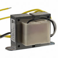
TCT40-01E07K
Description
XFRMR CNTRL 24VAC 1.67A 12" LEAD
Manufacturer
Triad Magnetics
Type
Standardr
Specifications of TCT40-01E07K
Maximum Power
40 VA
Primary Winding(s)
Single
Secondary Winding(s)
Single, No Center Tap
Series Output Voltage @ Current
24 VAC @ 1.67A
Mounting Type
Chassis Mount
Power Rating
40 VA
Dimensions
92.46 mm W x 56.38 mm H
Product
Control Transformers
Height
56.38 mm
Width
92.46 mm
Brand/series
TCT Series
Configuration
Enclosed
Frequency
50/60 Hz
Length, Lead
12 "
Mounting Hole Centers
3.13 "
Number Of Outlets
1
Phase
1
Power, Rating
40 VA
Standards
UL, cUL, cULus
Temperature, Operating
<+40 °C
Termination
Leadwires
Voltage, Primary
120 VAC
Voltage, Secondary
24 VAC
Weight
1.5 lbs.
Transformer Mounting
Chassis
External Height
2.22"
Peak Reflow Compatible (260 C)
No
Transformer Type
Control
External Width
3.64"
Supply Voltage
120V
Rohs Compliant
Yes
Primary Voltages
1 X 120V
Secondary Voltages
1 X 24V
Approval Bodies
CSA / UL
Leaded Process Compatible
No
Lead Free Status / RoHS Status
Lead free / RoHS Compliant
Parallel Output Voltage @ Current
-
Lead Free Status / Rohs Status
Lead free / RoHS Compliant
Other names
237-1240


P o w e r Tr a n s f o r m e r s
C h a s s i s M o u n t : C o n t r o l
: :
Triad control transformers supply secondary voltages that are commonly
utilized in various electronic, electro-magnetic and electrical control
conditions. These include such applications as use with relays, solenoids,
small motors, speed changers, pumps, heating elements, control valves
for fluids and gases, fans and blowers, electronic tubes, automatic
assembly equipment, recording devices, elevators, door openers, and
low voltage lamps.
: :
: :
CT = Center Tap
Section
T e c h n i c a l N o t e s
1. Hi-pot tested at 1,500 VRMS.
2. Secondaries may be connected in series or parallel for expanded voltage and
current ranges. See Control Transformer Connections diagram.
3. Transformer termination is solder lug.
D e s c r i p t i o n
P r i m a r y , 1 1 5 / 2 3 0 V o l t s / S e c o n d a r i e s , 6 / 1 2 / 2 4 V o l t s
O u t l i n e D i m e n s i o n s
B
D
G
A
C
E
F
Mounting hole sizes: Z =
F-105Z
F-211Z
F-106Z
F-212Z
F-107Z
F-213Z
F-398U
F-108U
F-214U
F-399U
F-400U
F-109U
F-215U
Type
No.
48.0 V CT @ 4.0A
12.0V CT @ 1.0A
48.0V CT @ 0.25A
12.0V CT @ 2.0A
48.0V CT @ 0.50A
24.0V CT @ 2.0A
48.0V CT @ 1.0A
24.0V CT @ 3.0A
24.0V CT @ 4.0A
48.0V CT @ 2.0A
24.0V CT @ 6.0A
48.0V CT @ 3.0A
24.0V CT @ 8.0A
Series
3
/
C a s e T y p e Z
16
" U =
Secondaries
13
/
64
x
3
/
8
"
24.0V @ 0.5A
24.0V @ 1.0A
12.0V @ 4.0A
24.0V @ 2.0A
12.0V @ 6.0A
12.0V @ 8.0A
24.0V @ 4.0A
12.0V @ 12.0A
24.0V @ 6.0A
12.0V @ 16.0A
24.0V @ 8.0A
6.0V @ 2.0A
6.0V @ 4.0A
Parallel
144
192
12
24
48
72
96
VA
: :
Primary: 115/230 VAC, 50/60 Hz
VA Range: 12 to 192
Secondary: 6/12/24 VAC
Case
Type
Z
Z
Z
U
U
U
U
S p e c i f i c a t i o n s
C a s e T y p e U
Connec-
tions
Lugs
Lugs
Lugs
Lugs
Lugs
Lugs
Lugs
C o n t r o l T r a n s f o r m e r C o n n e c i o n s
2
2
3
3
3
4
4
4
3
/
3
H
/
1
13
13
/
3
3
3
8
/
4
/
/
8
/
/
4
16
16
32
32
Dimensions
2
3
3
3
2
3
3
3
W
7
/
1
/
5
13
13
/
1
7
7
8
/
8
/
/
8
/
/
8
16
16
16
16
1
2
2
2
3
3
3
3
3
D
/
13
3
3
1
/
/
9
4
/
/
7
/
/
8
16
2
16
16
8
2
MW
2
3
2
2
2
2
2
3
13
/
1
1
1
1
3
3
/
/
8
/
/
/
/
/
Dimensions
8
4
16
4
2
4
4
Mounting
MD
2
2
2
2
•
•
•
•
•
•
3
3
7
1
1
5
/
/
/
/
8
4
4
8
1.000
0.678
1.500
1.050
2.500
2.250
4.250
4.250
3.240
5.900
6.060
Lbs.
8.00
Wt.
Related parts for TCT40-01E07K
Image
Part Number
Description
Manufacturer
Datasheet
Request
R

Part Number:
Description:
XFRMR CNTRL 24VAC 1.67A 12" LEAD
Manufacturer:
Triad Magnetics
Datasheet:

Part Number:
Description:
XFRMR CNTRL 24VAC 1.67A QC .250
Manufacturer:
Triad Magnetics
Datasheet:
Part Number:
Description:
XFRMR CNTRL 24VAC 1.67A QC .250
Manufacturer:
Triad Magnetics
Datasheet:
Part Number:
Description:
XFRMR CNTRL 24VAC 1.67A 12" LEAD
Manufacturer:
Triad Magnetics
Datasheet:
Part Number:
Description:
XFRMR CNTRL 24VAC 1.67A QC .250
Manufacturer:
Triad Magnetics
Datasheet:
Part Number:
Description:
XFRMR CNTRL 24VAC 1.67A 12" LEAD
Manufacturer:
Triad Magnetics
Datasheet:
Part Number:
Description:
XFRMR CNTRL 24VAC 1.67A QC .250
Manufacturer:
Triad Magnetics
Datasheet:
Part Number:
Description:
XFRMR CNTRL 24VAC 1.67A QC .250
Manufacturer:
Triad Magnetics
Datasheet:
Part Number:
Description:
XFRMR CNTRL 24VAC 1.67A 12" LEAD
Manufacturer:
Triad Magnetics
Datasheet:

Part Number:
Description:
Aluminum Electrolytic Capacitors Mr Series
Manufacturer:
TRIAD MAGNETICS
Datasheet:
Part Number:
Description:
Audio Transformers
Manufacturer:
TRIAD MAGNETICS
Datasheet:
Part Number:
Description:
Specifications: Kit Type: Common Mode Chokes for EMI ; Lead Free Status: Contains Lead ; RoHS Status: RoHS Non-Compliant
Manufacturer:
Triad Magnetics
Datasheet:
Part Number:
Description:
Aluminum Electrolytic Capacitors
Manufacturer:
TRIAD MAGNETICS
Datasheet:
Part Number:
Description:
Aluminum Electrolytic Capacitor
Manufacturer:
TRIAD MAGNETICS
Datasheet: