10961 3M, 10961 Datasheet

MDR CUTTING UNIT

10961

Manufacturer Part Number
10961
Description
MDR CUTTING UNIT
Manufacturer
3M
Series
MDRr
Type
Cutting Unitr
Datasheet

Specifications of 10961

Tool Type
Cutting Unit
Description/function
Cutting unit for 3M Handpress 10960-2000
Rohs Compliant
YES
Lead Free Status / RoHS Status
Vendor undefined / Vendor undefined
Other names
90169008567
JE150172870

Available stocks

Company
Part Number
Manufacturer
Quantity
Price
Part Number:
10961T
Manufacturer:
ST
0
3
Instructions
For the Assembly of the MDR 101XX-6000
Wiremount Plug using the 10960-2000 MDR
Assembly Press and Related Accessories
The assembly of the MDR plug
requires the following tooling which
must be ordered individually prior to
any tooling set-up:
Figure 1. 10960-2000 Hand Press
• 10960-2000 .........Hand Press (Fig. 1)
• 10961 ..................Cutting Unit (Fig. 5); includes
• 10962-2000 .........Fixture Unit (Fig. 14); includes
• 10964-1 ...............Cable Clamp (Fig. 13); Black,
• 10964-2 ...............Cable Clamp (Fig. 13); Silver,
Optional:
• 10963-2000 .........Fixture Block (Fig. 12); Not required
2 spare blades (10970-9)
14, 20, 26, 36, 40, 50, 68, 80, and
100 position connector stops
14-50 position
68-100 position
for initial unit; only needs to be ordered
when additional stations are set-up.
Must also order another 10962-2000.
1
Initial Tooling Set Up
1.
2.
3.
4.
5.
Figure 2. Back of press
Unpack the items listed above and set them on a
clean work bench.
Select the 10960-2000 Hand Press and place it in front of
the operator so the handle is toward the operator. It is
recommended for assembling connectors that the press be
positioned in a manner so cable may hang freely below
the press when moving the shuttle block (C of Fig. 4).
Locate the thumbscrew (C of Fig. 2) at the back of the
press. Loosen the thumbscrew and gently lower the
armature of the press away from the operator (Fig. 3).
This allows easy access to the back of the press
to install the cutting unit.
Slide the platen assembly forward using the side bar
which has a round black knob (B of Fig. 4) on the
operator’s left side.
Select the 10961 cutting unit (Fig. 5). Install cutting unit
from the rear of the press. The “A” portion of the cutting
unit faces the front of the press with the “B” portion
going toward the back. Slide cutting unit forward
in the two grooves provided.
A.
Stop bracket
B.
Stop bracket
thumbscrew
C.
Thumbscrew
for press
D.
Shuttle
stop
2

10961 Summary of contents

Page 1

... Figure 2. Back of press 5. Select the 10961 cutting unit (Fig. 5). Install cutting unit from the rear of the press. The “A” portion of the cutting unit faces the front of the press with the “B” portion going toward the back. Slide cutting unit forward 1 in the two grooves provided ...

Page 2

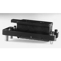
... Close plates manually by squeezing them together. B Figure 5. 10961 Cutting Unit 3 12. Push shuttle, with fixture unit and gauge block, away from the operator to the rear of the press until it stops. 13. Pull the press handle down, toward the operator, until the platen contacts the gauge block ...

Page 3

Grasp the stop so the numbers face up, the rounded end to the rear and the grooved end facing the operator. With the grooved end raised up, slide the back end against the small spring that contacts the stop ...

Page 4

Figure 8. Wires in “U” slot cover Figure 10. Cut wires E. Repeat for the next conductor, except position it to the rear and right. Place the next wire in the left slot (adjacent to the first one), followed by ...

Page 5

Blade Replacement Remove the cutting unit (Fig. 5) from the press. Loosen the set of hex screws on each side of the cutting unit, approximately two turns. Blades may now be removed. Install new blades* ensuring the beveled edge is ...

Page 6

... UNDER ANY LEGAL THEORY, INCLUDING BUT NOT LIMITED TO NEGLIGENCE OR STRICT LIABILITY, FOR ANY INJURY OR FOR ANY DIRECT OR CONSEQUENTIAL DAMAGES SUSTAINED OR INCURRED BY REASON OF THE USE OF ANY OF THE SELLER’S PRODUCTS THAT WERE DEFECTIVE. Printed on recycled paper Litho in the USA © 3M 1994 34-7035-7169-4 (XXXX.X) ...