3640 3M, 3640 Datasheet - Page 3
3640
Manufacturer Part Number
3640
Description
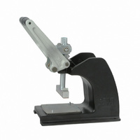
STANDARD BENCH PRESS
Manufacturer
3M
Type
Pressr
Datasheet
1.3640.pdf
(5 pages)
Specifications of 3640
Description/function
Hand press assembly
Lead Free Status / RoHS Status
Not applicable / Not applicable
For Use With
PAK 50E and 50
Other names
0-00-54007-31556-8
00054007315568
3640
3M9426
5400731556
54007315568
80-6100-7882-8
80610078828
00054007315568
3640
3M9426
5400731556
54007315568
80-6100-7882-8
80610078828
Available stocks
Company
Part Number
Manufacturer
Quantity
Price

Part Number:
36401C
Manufacturer:
MURATA/村田
Quantity:
20 000
Part Number:
36401E0N2BTD
Manufacturer:
TETYCO
Quantity:
20 000
Part Number:
36401E0N4BGTD
Manufacturer:
TETYCO
Quantity:
20 000
Part Number:
36401E12NJSTD
Manufacturer:
TETYCO
Quantity:
20 000
Part Number:
36401E1N0BTD
Manufacturer:
TETYCO
Quantity:
20 000


Connector Assembly
Note: For clarity, the pictures show the cable and
connector being positioned on the locator plate
while it is on the table top. This can also be done
while the plate is in position on the press.
The 3M
terminated to two pieces of 3M
is somewhat unusual for an insulation displacement
style connector. The connector has two rows of
contacts. One row of contacts protrudes further from
the connector body than the other. Each row will
terminate one of the two pieces of cable. One piece
of cable will end up against the connector body.
Cover 2 will end up between the two pieces of cable.
The second piece of cable will be on top of Cover 2.
Cover 1 will latch to the body and be on top of the
second piece of cable.
1. Place Cover 1 into the slot on the locator plate.
2. Place the first piece of cable against the cable
3. Maintain pressure on the cable with your hand to
4. Cover 2 has a cable stop rib on one edge. Place
guide, between the plastic latches on Cover 1,
and with its end against the cable stops. When
the cable is pressed against the ridges on the
surface of the locator plate, it will become square
to the cover groove and the cover should slide
into position aligned with the cable. Make sure
that the cable is in the grooves on Cover 1.
keep the cable in position.
Cover 2 on top of the cable and between the
latches of Cover 1. The cable stop ridge should
be on the edge of Cover 2 that is in the center of
Cover 1.
™
PAK 50 Connector is made to be
™
3365 Cable. This
3
Cable guide
PAK 50E Connector
Connector Assembly Steps 1, 2, 3
Connector Assembly Step 4
Cable Placement
PAK 50E
No. 2 Cover
Cover 2
Cable Stop
Base Cover
Cover 1
78-8133-3511-0-A